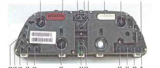
Description of signs and symbols on the Niva instrument panel, panel repair, combination diagram
1 – plug connector block with conventional numbering of plugs;
2 – tachometer; 3 – voltage stabilizer; 4 – instrument cluster lighting lamp; 5 – coolant temperature indicator; 6 – fuel level indicator; 7 – resistor 470 Ohm, 0.25 W; 8 – resistor 36 Ohm, 5 W; 9 – warning lamp of the toxicity reduction system; 10 – control lamp for heated rear window; 11 – fog light indicator lamp; 12 – control lamp for high beam headlights; 13 – indicator lamp for external lighting; 14 – indicator lamp for direction indicators; 15 – voltmeter; 16 – brake fluid level warning lamp; 17 – diode IN4002;
1 – tachometer; 2 – voltage stabilizer; 3 – instrument cluster lighting lamp; 4 – coolant temperature indicator; 5 – fuel level indicator; 6 – warning lamp of the toxicity reduction system; 7 – indicator lamp for heated rear window; 8 – fog light indicator lamp;
9 – control lamp for high beam headlights; 10 – indicator lamp for external lighting; 11 – indicator lamp for direction indicators; 12 – voltmeter; 13 – brake fluid level warning lamp; 14 – oil pressure warning lamp; 15 – differential lock warning lamp; 16 – fuel reserve warning lamp;
Let us remind you that on the website you can find reports on the modification or repair of a domestic SUV.
Key words: 4x4 instrument panel
Found an error? Select it and press Ctrl Enter..
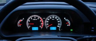
The diagram of the VAZ 21213 instrument cluster is shown above, the designation of the control panel elements is as follows:
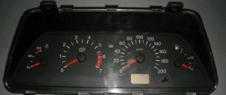
- Coolant temperature controller, which also informs the driver about the engine temperature. If the sensor needle rises above the optimal value (enters the red zone), you must stop and turn off the engine to prevent it from overheating. Before further operation of the car, it is necessary to determine the causes of overheating of the internal combustion engine.
- A tachometer that tells the driver at what speed the crankshaft is moving. If the number of revolutions exceeds the permissible value and the arrow moves into the red zone, this may negatively affect the functionality of the engine as a whole.
- Left turn signal activation indicators, turns on only when the steering column switch is switched.
- Right turn signal.
- Speedometer, thanks to which the driver can know at what speed his Niva 21213 injector is traveling.
- Fuel level controller in the tank.
- A symbol that lights up when there is insufficient gasoline in the tank. If this lamp lights up, then there are less than 6 liters of fuel left in the tank.
- Dimensional lighting.
- The Niva instrument panel is also equipped with a brake emergency light. It may appear when the volume of fluid in the hydraulic drive reservoir has dropped below the permissible level. Operation of a car with such a problem is not allowed until it is eliminated.
- Distant lighting.
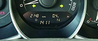
- Key for resetting daily mileage readings. To reset the values, the button must be pressed for five seconds, while the car must stand still.
- Mileage traveled by the car. The total mileage is indicated at the top, and the daily mileage at the bottom.
- An indicator indicating the need for engine diagnostics. When the ignition is turned on, this indicator always lights up; it should go out after the engine starts. If the lamp continues to burn, this indicates that not everything is in order with the engine.
- Hazard warning lights.
- Clock, outside temperature.
- Battery charge icon.
- The handbrake activation symbol should always light up in red.
- A light indicating a lack of engine fluid level always appears when the ignition is turned on, and after starting the engine it should go out. If the light remains on, this indicates that oil needs to be added to the engine.
- Reserve indicator (video author - Andrey Vlasov).
Differential
This mechanism is a kind of distributor of traction forces coming from the motor to the wheels. An important feature is that the latter have the ability to rotate at different speeds. The importance of having a differential mechanism is due to the fact that during turning maneuvers, the wheel located inside makes fewer revolutions when compared with the number of turns of the outer wheel.
In the absence of a differential mechanism, this would cause detrimental consequences, such as wear and damage, because the result would be the following: when turning, one wheel would be in a slip state, and the second would simply rub against the road surface. The design features of the Niva transmission provide for the presence of 3 differentials. They are located in each of the bridges and in the transfer mechanism.
When the car moves on a flat road and in a straight line with differentials, the traction force is divided equally between all 4 wheels. If there is insufficient adhesion of the wheels to the surface or slipping occurs, the differentials will redistribute the load on the slipping and sliding wheel so that the first receives more force, and the second, accordingly, less.
We have already mentioned UAZ. Despite many similarities, it should be understood that the VAZ’s all-wheel drive is made in the “pat-time” style. This means that when connected, the axes are firmly connected to each other, and rotation occurs at the same speeds. This device imposes some restrictions on the use of all-wheel drive - it can only be used in cases where road conditions allow slipping. In cases with hard asphalt roads and highways, it is recommended to switch the car to single-drive mode.
Video “Laying wiring in the sports version of the Niva”
You can learn more about this process from the video (author - Suprotec Racing channel).
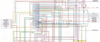
Currently, problems with a car’s electrical system can be corrected at any car service center, but for those who like to fix everything themselves, an electrical circuit will come in handy. The electrical diagram of a VAZ 21214 with an injection engine is a graphical representation that shows the order and connection of the elements in the circuit, but does not show the actual arrangement of the elements. But even the most inexperienced car enthusiast will be able to understand something in the electrical circuit of the VAZ 21214 and fix a small malfunction on his own, which will help save time and money.
Tips for owners
To make driving your car comfortable, read some important points:
- The usual, standard arrangement of the front and rear handles is forward and backward, respectively. Movement in this mode can and should be carried out in areas characterized by even and smooth surfaces.
- Locking the differential by switching the front handle to the rear position is best on roads characterized by increased slipperiness. This measure will give Niva stability. It is worth understanding that after overcoming the problem area, the handle will need to be returned to its original position.
- As noted earlier, downshift should be activated before a potential obstacle, but not while the car is already stuck.
- It is worth understanding that activating the lock when the vehicle is stationary is sometimes impossible, even if the clutch is depressed. This may be caused by the clutch teeth hitting the gear teeth. In this case, you can try to activate the lock by starting to drive slowly and make a slight turn. If problems arise with disabling the lock, it is recommended to perform the same procedure with the clutch depressed and the steering wheel slightly rocked.
And also interesting: Tikhaya Niva - it’s now possible - BEHIND THE STEEL - MirTesen media platform
Dashboard Lada 4×4 COMFORT (new model) VAZ 21213-21214 reviews
For any online payment option from a private individual, a fiscal receipt will be sent to your email in electronic form in full compliance with the law on the use of cash register equipment 54-FZ, which does not give you any additional reason to worry about our store)
The following payment methods are available in our online store:
— FOR INDIVIDUALS, payment for orders is carried out in real time on the website of the ROBOKASSA payment system, 0% for transfers: plastic cards of any banks, credit cards, mobile payments (MTS / Beeline / Tele2), electronic money (Yandex.Money, WebMoney) and more (Samsung Pay, Viber) .
— FOR LEGAL ENTITIES (LLC and individual entrepreneur of the Russian Federation), through any bank on an issued invoice (non-cash payment) “without VAT” , by transferring funds to a current account.
Note ! After your first purchase, you can use the VS-AVTO BONUS PROGRAM to pay for your order.
Please note that delivery is at the customer's expense and is not included in the initial cost of the order.
The term for the formation and dispatch of an order is from 3 working days after receipt of payment to our accounts in accordance with the offer agreement and depends on a number of factors: movement of goods between warehouses, part painting, individual tailoring/execution.
After sending your order, you will be sent an email notification with the tracking number of the shipment, using which you can track the movement of the cargo on the carrier’s website.
An order for pick-up is made upon full prepayment of the order (after placing an order on the website, please wait for it to be confirmed by managers). The order is received at the pick-up point during business hours.
Delivery point address:
RF, Samara region, Tolyatti, GSK "Plamya", st. Officer 14
Pick-up point opening hours:
daily 8:00 - 19:00, Moscow time
Delivery is carried out by Russian Post with 100% payment for the order and delivery. The cost and approximate terms are calculated individually upon confirmation of the order. As a Federal client of Russian Post, we can provide the most favorable delivery rates from 200 rubles. depending on size, weight, value and remoteness of the region. We ship from Tolyatti 5 days a week (Monday - Friday).
Note! The shelf life of parcels at Russian Post offices is up to 15 days! In this case, a repeated notification will not be sent to the address specified in the parcel.
Delivery to the departure terminal in Tolyatti is free of charge, the rest of the delivery cost is paid by the customer upon receipt at the TK terminal in your city. The advantages of delivery using TC include the absence of restrictions on the volume and weight of goods.
Attention! Sending parts made of plastic, glass, abs, glass mat, etc. Recommended by transport companies only in rigid packaging (crate)!
Delivery times are determined by the transport company and are their area of responsibility. VS-AVTO cannot influence delivery times once the cargo has already been sent.
In connection with the amendments dated July 6, 2021 to Federal Law No. 374-FZ “On Combating Terrorism”, as well as the adoption of the anti-terrorism “Yarovaya package”, from July 20, 2016, in order to send cargo, the sender must provide information about himself, the recipient and payer. In particular, our clients require identification document details (Russian passport, driver’s license).
For customers from Kazakhstan, to send an order by transport companies, you must indicate the IIN.
Removal and installation instructions
How to remove and install the dashboard on a Niva:
- First, you need to remove two plugs from the control panel lining and unscrew the screws. Next, unscrew the screws that secure the tidy visor.
- The right side of the panel facing is pulled out, the pads from the keys are removed, as well as the connector. Next, the control panel trim is removed from the left side; by doing this, you can dismantle the button for activating the side lights and optics. After this, the panel lining can be completely dismantled.
- The two screws of the tidy are unscrewed, the shield itself is removed, and all connectors and plugs are disconnected. If there are problems with the operation of the shield, they are resolved at this stage. The device is being repaired, it is soldered, and burnt-out light bulbs are replaced.
- Next, the shield is installed. When installing, keep in mind that the holes in the steel strip located under the tidy must line up correctly. Further installation is carried out in the reverse order of removal.
The differential lock on the Niva is a faithful assistant to the driver
All-wheel drive does not always provide off-road capability. Often this is not enough. When, as on the Niva, the locking works in conjunction with all-wheel drive, we can say that the car is at least close to all-terrain vehicles. And with such a car it is quite possible, if not to conquer the muddy roads, then to move quite safely along country and abandoned roads.
But do not forget that differential locking is a mode for difficult driving conditions. But there is no need to be afraid of him. We must remember that blocking allows the Niva to drive where others will not even try to do so. But you shouldn’t turn it on unnecessarily in the city. This is fraught with excessive gasoline consumption, tire wear, and ultimately, car breakdown.
Feedback and questions
VAZ 2121 or Lada 4x4 has been produced since 1977. During the entire production period, the body of the SUV changed slightly, and the interior was modified, for example, changes concerned the instrument panel. Let's look at the types of Lada 4×4 dashboards and their descriptions.
The most common instrument combinations (catalog numbers):
- 2121-5325120 - the very first model;
- 21213-3801010 - intermediate model;
- 21150-3801010 - modern model.
Despite the fact that the instrument panels are different, the indicators showing the status of the vehicle systems remain unchanged and are divided by color:
- Green and blue lamps are informational;
- Yellow lamps are informative (Attention!);
- Red lights are emergency lights, movement is prohibited!
Let's look at the description of the instrument panel using the latest VAZ 21214 model as an example.
- coolant temperature indicator. Red zone - engine overheating. When the arrow reaches it, you must stop the car, turn off the engine and check the serviceability of the cooling system;
- tachometer. Shows crankshaft rotation speed. Do not allow the arrow to go into the red zone;
- left turn indicator. Lights up when the left turn signal is turned on;
- right turn indicator. Lights up when the right turn signal is turned on;
- speedometer. Shows the actual speed of the SUV;
- fuel level in the gas tank. 0 - the tank is empty; 1/2 - half of the fuel tank; 1 — full gas tank;
- Fuel reserve indicator lights up when there is less than 9.5 liters of gasoline left in the fuel tank. Do not let the fuel run out, this may damage the fuel pump;
- indicator for turning on external lighting. Lights up when the exterior lighting is turned on;
- low brake fluid level indicator. Lights up when the brake fluid level in the reservoir is below the minimum allowable level. Driving with this lamp on is prohibited;
- high beam headlight indicator. Lights up when switching the headlights from low to high;
- daily mileage reset button;
- odometer display. The upper numbers are the total mileage of the vehicle, and the lower numbers are the daily mileage;
- hazard warning indicator. Lights up when the emergency lights are turned on;
- engine management system malfunction indicator (CheckEngine). It is necessary to read error codes from the ECU using an on-board computer or diagnostic equipment;
- battery charge indicator. Lights up when electrical equipment starts running on battery power;
- handbrake indicator. Lights up if the handbrake is on;
- emergency oil pressure indicator. Lights up if the oil pressure in the engine lubrication system drops below normal. Operating the engine with the lamp on is prohibited. Check the engine oil level and the serviceability of the filter;
- reserve.
Traffic in winter
Warning. Be very careful on wet or slippery roads - avoid sudden braking and sudden pressing and releasing of the accelerator pedal. Drive the car smoothly, without sudden movements of the steering wheel. Reduce speed only by gradually shifting to lower gears with partial braking using the service brakes. If, no matter what, the car begins to skid, turn the steering wheel in the direction of the skid and smoothly use the steering wheel and gas pedal to level the car.
At road intersections, ice often forms due to wheel slipping when starting off. Therefore, when approaching such places in advance, on a dry area, begin to reduce your speed.
In winter, it can be difficult to move away from a slippery area. To do this, engage second gear and, slowly releasing the clutch pedal, gradually increase engine speed. In some cases, it is useful to lock the center differential before driving.
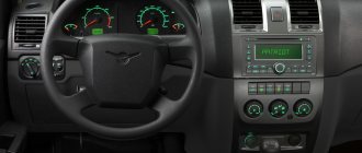
NIVA control panel
Installation of the Lada Comfort dashboard for NIVA
Preparing for installation
The quality of the panel product is excellent, the coating is soft and not squeaky. The panel is supplied without the glove compartment lid, side air ducts and climate system lighting elements, brightness control and hydraulic corrector.
For those who have a Niva produced no earlier than 2010, there will be no problems with components. I had an adapter panel installed and had to buy an additional glove compartment lid and two mounting brackets for the Niva instrument panel - left and right
Glove compartment lid and brackets
Next, I began preparing the panel for installation. To begin with, I attached the lighting elements “climate system” to the “beard”
I covered all the joints of the parts with anti-squeak, and covered the inside of the glove compartment with bitumen-impregnated foam rubber and anti-squeak.
Interior of the glove compartment
Then the question arose of how to close the hole intended for installing the on-board computer. At first I thought about setting the clock to ten, but then I found a monitor with a rear view camera on Ali. Once I received the camera, I installed it on the panel and at the same time mounted the central deflectors, the main light button, the radio bracket and the three-position switch for the main stove.
Installed the glove compartment lid
Then, to seal, I glued all the joints on the central and side air ducts
Side duct before sealing
Pasted on the inside
Central air duct before sealing
Then I prepared the car itself for installing the panel. Vibration and sound insulation was glued, the wiring was put in order to replace the fuses with flag fuses, and an air duct for the ventilation system was installed. The steering wheel has been removed.
In addition to everything (no photo), holes were drilled to the left of the steering wheel for the trunk opening buttons and control of the “+” solenoid of the winch. The steering column casing is covered with anti-squeak. The carburetor choke cable is installed in the panel. At this point, the preparation process was completed and moved on to the installation process of this product.
Installation of the Lada Comfort panel for NIVA
After carrying out the preparatory activities, I proceeded to install the panel on the car. The installation began with the installation of the main part of the panel. First, I inserted the “choke” cable through the hole in the body. I connected the wires of the trunk opening buttons and the winch “+” solenoid control. I installed the panel in place. Since the panel was made a little wider than the opening under it, it was necessary to use force to stick it in place. This took about 1.5 hours. Then I secured the panel on top with 4 M6 nuts and washers, and on the bottom with 4 self-tapping screws. Connected the backlight brightness control.
Installed the panel base
Then there was a problem with the wiring. Length was limited. Therefore, I laid the wires for connecting the radio and monitor through the hole located next to the lower screw, and the wires for the sidebar buttons through the seat of the instrument unit. Next, on the “beard” I installed control buttons for the winch, additional heater, rear and front PTFs, rear heating and wipers. I secured the levers of the damper control unit and the heater tap with M6 screws.
I connected the wires and installed the “beard” in place, securing it with two screws from above to the panel and one screw from below to the floor lining.
Then I installed a radio in the central part of the panel, connected the wires to it, as well as to the monitor, the main stove switch and the main light button, and secured it to the panel.
I installed the instrument cluster, connecting two connectors and a speedometer drive cable to it. This is what happened in the end
I secured the inside of the glove compartment with three self-tapping screws.
Interior of the glove compartment
Result: the interior of the NIVA has been transformed, the glove compartment and shelf have been enlarged. The radio is now higher and you can’t touch the flash drive with the lever. A shelf for the phone and a rear view camera monitor appeared. I'm pleased with the result. I liked the workmanship.
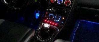
Making LED panels in Niva with your own hands
I have long been attracted by the idea of converting the dashboard lighting to LED. Since I want to replace my entire instrument panel with a more informative one, I decided to LED the instrument panel of my friend’s VAZ-21213, so to speak, to gain skills, and if I mess it up, it’s not a problem to buy another one.
1. LEDs 3 Volt - 5 pcs. I chose a regular size (like a lighter), only with diffuse red light emission. I chose red because... I myself drive an Audi with traditional factory red lighting and besides this color, I don’t know what is more pleasant and noble.
2. Superglue - 1 tube
3. Thin single-core wire with insulation - 30 cm.
4. Nail polish remover
6. A piece of plastic with a thickness of at least 1 mm and no more than 3 mm. What came into use was some plastic from a hammer drill that came to hand, on which there was a sticker from the manufacturer, dimensions, etc.
7. Soldering iron with solder and rosin.
8. Stationery knife
Without much effort, remove the front part of the panel, secured with bolts.
Eliminate vibration with additional fasteners
Installing the third support of the transfer case on VAZ 21213/21214 vehicles allows you to reduce the level of vibration of the transfer case; with this support it is easier to center the transfer case. The part can be purchased at auto stores or made yourself. The finished product comes with three long studs (for model 2121); to install the third support on this machine, you will need to unscrew the short studs from the transfer case housing and install new studs from the kit. We carry out repairs as follows:
- dismantle the front passenger seat in the cabin;
- remove the floor tunnel lining;
- in the cabin we move aside the carpet covering the body amplifier (in front of the handbrake lever);
- remove the transfer case (alternatively, you can simply hang it up, but removing the third support makes it easier to install);
- We attach the bracket of the new support to the body of the RC;
- we install the transfer case in place, center it in the optimal position, and fasten the side supports;
- we combine the third support with the body, drill two holes in the bottom;
- Using washers, bolts and nuts (from the kit) we attach the support to the bottom of the body.
Vibration is eliminated more effectively by installing a subframe under the transfer case. You can also make such a device yourself or buy a finished product at a car store.
In order to install the subframe, the transfer case must be removed. It is more convenient to carry out such work in a pit; we carry out repairs as follows:
- leave the car in neutral gear;
- disconnect the propeller shaft from the transfer case, it is advisable to mark the driveshaft flange and the drive shaft so that during installation, align the driveshaft according to the marks - this way, the occurrence of unnecessary vibrations is eliminated;
- dismantle the muffler mounting bracket;
- remove the gearbox traverse;
- jack up the transfer case, remove the side fastenings of the transfer case;
- We treat the places where the subframe fits to the body with Movil;
- place the subframe on the gearbox studs;
- we mark the attachment points of the subframe on the side members, drill holes, attach bolts to the body;
- we tighten all fastenings, except for the transfer case supports themselves;
- we perform alignment of the steering wheel;
- Finally tighten the transfer case supports.
It should be noted that installing an additional support or subframe on the steering wheel does not always lead to the desired effect; in some cases, vibration only increases.
Dashboard of VAZ 2121 Niva
The VAZ 2121 Niva is equipped with the very first modification of the dashboard 2121-5325120 (catalog number). Its characteristic features are a simple and convenient layout of control and measuring devices, an angular body, a glare-free lining, and an instrument panel that is clearly visible from behind the steering wheel.
The device of the instrument console panel of the VAZ 2121 Niva
The main control and measuring elements and control indicators of the VAZ 2121 instrument panel are:
speedometer, showing not only the current speed of the car, but also the daily and total mileage;
- tachometer - a device indicating the crankshaft rotation speed (the yellow part of the scale is the mode of increased crankshaft rotation speed, the red part is a critical mode that is unsafe for the engine);
- oil pressure sensor in the engine lubrication system and warning lamp for low pressure in the system (flashes red when the engine starts and then goes out);
- fuel level sensor and fuel reserve lamp (notifies the driver with a constant red light when there are 4-5 liters of fuel remaining in the gas tank);
- liquid temperature sensor in the engine cooling system (the light part of the scale is normal temperature, the red part is engine overheating, requiring checking the tension of the generator drive belt and cooling system);
- fluid level lamp in the hydraulic brake reservoir (a red light when the ignition is on indicates a drop in the level below the prescribed norm due to fluid consumption or as a result of damage to the system);
- differential lock warning lamp in the transfer case (lights up in orange when the ignition is on and the lever is set to the differential lock mode in the transfer case);
- trip odometer reset handle.
Another important indicator that allows the driver to monitor the performance of the generator and battery is the battery charge lamp, located to the left of the instrument panel. Under normal conditions, the indicator flashes red when the engine is turned on, and then goes off. However, if it continues to burn while the engine is running, this indicates a breakdown of the generator or a weakening of the tension of its drive belt.
Transfer case Niva 21214
The relatively complex scheme for distributing torque from the internal combustion engine to the wheels is explained by the universal purpose of the Niva 2121 - if used correctly, it can be used comfortably in the city and along muddy country roads. Such properties are ensured by the presence of a transfer case with a center differential lock, complementing a 4- or 5-speed manual transmission, depending on the year of manufacture.
(see also on this topic Driving a car and What is all-wheel drive, as well as Niva driving techniques)
TRANSFER CASE SHIFTING
Transfer case levers and their positions
H - low gear;
N - neutral position;
B - top gear.
P - differential unlocked;
B - differential is locked. When the lever is moved to this position, a warning light comes on in the instrument cluster, warning that the differential is locked.
Also interesting: Generator Niva 2121, 21213, 21214: which one is installed, replacement
NOTE Shifting from low to high gears and locking the differential can be done while driving with the clutch disengaged.
It is recommended to engage low gear in the transfer case after the vehicle has come to a complete stop and with the engine disconnected from the transmission.
To overcome difficult sections of the road, block the differential in advance. Do not lock the differential when the car's wheels are slipping. After overcoming such sections, unlock the differential - driving the car on good roads with a locked differential shortens the life of the power transmission mechanisms, increases tire wear and fuel consumption, and when braking the car can lead to skidding.
SHIFTING TRANSMISSION GEARS
Gear shift diagram (also printed on the handle)
Before driving, check the position of the transfer case levers - it must correspond to the road conditions. Start driving in first gear and, as the crankshaft speed increases, move to higher gears in a timely manner.
In time and in accordance with the road situation, change to a lower gear in the gearbox, avoiding overloading the engine.
To move in reverse, press the gear shift lever, pushing it all the way down and move it to the position corresponding to engaging reverse gear. Engage reverse gear only when the car is completely stopped.
The VAZ Niva series was developed as a universal all-terrain vehicle. These cars perform well in both off-road and city roads. One of the components that ensure high cross-country ability is a high-quality multiplier (distributor).
The transfer case is not present in all VAZ passenger cars, but only on cars with two drive axles. In the transmission, the transfer case (TC) is installed at the rear of the gearbox; a rear driveshaft is attached to its shank, which connects the transfer case to the rear axle. The front axle is also driven by the steering wheel; it is connected to the transfer case by a front driveshaft.
The reduction gear in the Republic of Kazakhstan is designed to obtain high torque, it is used to overcome difficult sections of the road, and helps to cope with off-road conditions. The VAZ Niva transfer case contains the following main parts:
- the body itself;
- front axle drive shaft;
- intermediate shaft;
- drive shaft;
- gears;
- bearings;
- differential housing;
- satellites;
- differential lock clutch;
- gear shift clutch;
- flanges (for connection to cardan shafts);
- oil seals;
- control levers.
For a long time, drivers of Soviet Nivas have been convinced that aligning the car’s transfer case significantly reduces vibration, noise levels in the cabin and saves fuel consumption. Therefore, if you have just purchased a VAZ-21213, then you should immediately start this work. When you purchase a car second-hand, you should not rely on all the promises and assurances of the previous owner.
Even if he assured that the alignment was carried out and everything was fine, it is best to check this fact and make sure of it. This work in itself is not difficult, but it requires additional hands, since the presence of an overpass cannot be done alone. Car service specialists recommend using a lift, because other devices require additional fastenings. The process itself is like this:
- one person sits in the driver’s seat, the car is lifted with him;
- the lock must be disabled and 4th or 5th gear engaged;
- it is necessary that the pins are in the middle of the support holes (to do this, move the dispensing supports apart with your hands);
- the second person from below must loosen the 4 nuts that secure the transfer case;
- the person in the driver’s seat must pick up speed and inform his partner about this (the assistant “on the go” tightens the clamps to the required level);
- in a car service center for centering, the car must pick up speed to 60 km/h (the speed must be set in 4th gear).
We recommend: How to properly clean sheepskin car seat covers?
It is important to know! On Niva 21213, the intermediate shaft is not a cardan, but a CV joint. For this reason, factory settings may dispense with height adjustment. But in the case when the dynamic alignment does not live up to expectations, you can try to tighten or lower the transfer case and repeat the alignment.
To repair the transfer case on a VAZ 21213 (21214), the unit must first be removed. We carry out removal in the following order:
- in the cabin we dismantle the plastic lining of the gearbox and gearbox levers;
- unscrew the knobs of the transfer case shift levers, remove the casing under them;
- disconnect the speedometer cable, for RK 21214 you will need to additionally disconnect the speed sensor;
- we unscrew the bolts with nuts securing the elastic coupling of the front and rear propeller shafts; in order to remove the bolts, the cardan shafts must be turned - they are removed one at a time in one specific position of the shaft;
- We install a jack (or other support) under the transfer case and mark the places where the side supports of the RC were attached. This is done in order to minimize the alignment of the transfer case during installation;
- unscrew the 4 nuts securing the gearbox to the gearbox;
- unscrew the 4 fastenings of the RC supports to the car body;
- Now all that remains is to dismantle the transfer case.
The transfer case mechanism includes more than 60 independent parts, which is confirmed by the presented drawing. Therefore, it is quite prudent to name the main elements and their purpose.
- Housing Differential housing Shafts Couplings Seals Pinions Gears Flanges Levers
A pair of gears are tightly seated on the drive shaft, one of them (large) is intended for high gear, the second (small) is responsible for low gear. They have serrations with straight and oblique profiles. The first ones are in contact with the coupling, the second ones - with the intermediate shaft. The inclusion of one or another row causes the coupling to move along the hub in the horizontal direction, after which it is connected to the gear on the transfer case drive shaft.
The intermediate position turns off the gearbox (the gearbox is open), and the vehicle cannot be moved in this mode. The front helical gear on the intermediate shaft is used to control the differential. The locking is engaged, or the rigid coupling of the drive shafts of both axles, is carried out through a clutch. The design is typical for modifications 21213 and 21214, and the latter is additionally equipped with a speed sensor drive.
In the operating state (with the transfer case reduction gear connected), the gear ratio in the first stage changes from 4.4 to 7.83, the second - from 2.52 to 4.58, the third - from 1.63 to 2.9, in the fourth - from 1.2 to 2.14, fifth - from 0.98 to 1.75, which is expressed in an increase in traction on the wheels.
The normal position for the RK handles, ensuring adequate behavior on the road of good quality:
- Front - away from you Back - towards you
The special operating mode of the transmission is switched on not long before the car begins to overcome an obstacle (rut, mud, ford or rise). The transition to the lowest row must be done while stopping. Returning to top gear is allowed on the go, although it causes problems for beginners due to the lack of the usual synchronizer.
It is somewhat more difficult to properly handle the forced manual locking of the center differential. On the contrary, it turns on when the car moves slightly (up to 20 km/h) due to misalignment of the grooves on the locking clutch, satellites and ring gear. To simplify turning the lever into the desired position, taking into account the Niva 2121 transfer case, pick up a small speed, then, shaking the steering wheel, pull the handle towards you.
Problems can also arise when disengaging the lockout, as the clutch teeth literally catch on the ring gear. Engage reverse and, rocking the steering wheel, push the lever away from you. This action is performed immediately after overcoming a difficult section in order to avoid overloading the gearbox. It is most effective to disable the differential together with the transition to lower stages.
And also interesting: Chevrolet Niva or Niva 2121: which is better, reviews from owners “
Model VAZ-21213 is an all-terrain passenger car with permanent all-wheel drive and differential lock. Brand 21213 is a restyled version of the first VAZ SUV, VAZ-2121. RK Niva 21213 has three gears:
- the first - with a gear ratio of 1.2;
- the second, lowered – with the number 2.135;
- neutral
21213 is equipped with 4-speed and 5-speed gearboxes, and when the first speed of the transfer case is turned on, the car operates in standard mode, the gear ratios in the transmission are from 5-speed. The checkpoints are as follows:
- 1 – 4,4;
- 2 – 2,52;
- 3 – 1,63;
- 4 – 1,2;
- 5 – 0,98.
Instrument cluster
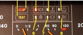
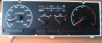
The figure below shows an instrument cluster that contains the following indicators:
1 – coolant temperature. If the arrow moves into the red zone, you should stop immediately, because The engine gets very hot;
Something to remember! It is prohibited to operate a vehicle with an overheated engine. It is necessary to take the car to a service station to determine and eliminate the cause of engine overheating;
2 – tachometer. Designed to inform the driver about the crankshaft rotation speed. The red zone of the indicator indicates that the engine is running at high frequency, which can be detrimental to the engine;
3, 4 – indicator lamps for turning on left and right turns, respectively. Lights up with green flashing light;
6 – fuel level;
7 – fuel reserve. Orange color. Lights up if the amount of fuel remaining is less than 6 liters;
8 – side light indicator;
9 – brake emergency indicator. Red color. Lights up if the fluid level in the brake hydraulic reservoir is below the min mark;
Something to remember! It is prohibited to drive a vehicle with the emergency brake indicator on.
10 – high beam. Blue color;
11 – “Reset readings” button;
12 – vehicle mileage. The top line shows the total mileage, and the bottom line shows the daily mileage. To reset the daily odometer readings, you need to hold down button 11 for 5 seconds. The car must not move;
13 – “Check engine” lamp. When the ignition is turned on, the indicator lights up; if there are no faults, the lamp goes out. If any problems are detected, the light is constantly on;
14 – indicator of the included alarm system. Red flashing color;
15 – indicator of on-board network, clock, temperature;
Engine management system Lada 4×4 (VAZ) 2121 Niva / Lada 4×4 (VAZ) 2131 Niva
Removing the speed sensor
We carry out the work on an inspection ditch or overpass.
Turn off the ignition. From the bottom of the car, on the front of the transfer case, we compress the spring clamps of the wiring harness block of the engine management system.
. and disconnect the block from the speed sensor.
There is a metal washer installed on the driven gear shaft - do not lose it.
Install the vehicle speed sensor in reverse order. In this case, the speed sensor shaft should fit into the hole of the drive gear shaft.
Vibration
Vibration in the body is the main “disease” of the Niva; it often occurs due to improper alignment of the transfer case. Most often, vibration occurs on VAZ 21213/21214 cars, since the transfer case is mounted only on two supports on the sides of the body; on the Chevrolet Niva, the transfer case is already installed on three supports. But before you start adjusting the position of the transfer case, you should check the condition of other parts of the chassis - vibration can occur for other reasons:
- driveshafts are poorly secured;
- wheels are not balanced;
- there is play in the cardan crosspieces (vibration is especially affected by play in the rear driveshaft crosspieces);
- The vibration comes from the engine itself.