Internal combustion engines require fuel and an igniter to operate. The ignition module plays this role on fuel-injected cars.
The article will describe checking the VAZ-2114 ignition module with a multimeter.
The purpose of the ignition module (IM), operating principle, and main malfunctions will also be described in detail.
Purpose and principle of operation
The ignition module of a VAZ-2114 car with an injection 8-valve power unit is located directly opposite the engine block on the spark plug side. This arrangement is most effective for supplying high-voltage wires to the spark plugs. The device is mounted on the wall of the engine compartment. This position was not chosen by chance. This way the MH interacts less with vibrating parts of the car.
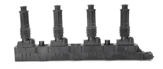
The device that comes with the described car model is of the block type. One housing contains 2 inductors and 2 discharge voltage regulators. The device operates according to the following principle:
- A pulse signal passes from the crankshaft position controller to the on-board computer.
- The signal is confirmed by a pulse signal from the Hall sensor of the ignition system.
- Both signals are calculated in the on-board computer and transmitted as current to the module.
- The module converts 12 volt voltage into high current.
- From the coil, the voltage is supplied to the spark gap, which forms a pulse voltage.
- The voltage passes through the high voltage wire of cylinders 1 and 4 to the spark plug.
- The spark plug is discharged by a spark, igniting the fuel in the cylinder.
- During the discharge, spark plugs 2–3 also receive voltage, but its power is adjusted by the spark gap.
All components are made of high-strength plastic with an aluminum plate for mounting to the engine. Additionally, both coils are filled with insulating solution. On the body of the device there are only 4 contact sockets for high-voltage wires and an electrical power socket.
Subject to all operating rules, the ignition module is a very reliable electronic device, but it is quite fragile. If the electrical circuit has a number of damages and is often subject to short circuits, then the coils or arresters fail.
Any malfunction of the MH leads to interruptions in engine operation. The following will describe the main symptoms of a malfunction of this device.
What does the ignition module consist of?
The ignition module built into the VAZ-2114 consists of 2 high-power transformers and the same 2 electronic-based control units. One side of the product has 4 outputs at once; they are responsible for connecting the candles. To keep the structural components in their original form and protect them, the manufacturer provides a plastic coating. The weight of the entire structure slightly exceeds 1 kg.
The spark plugs suitable for the engine are fixed together with the ignition module by running high-voltage wiring. A device called a “controller” controls the process. First, he takes the performance indicators of the structure, then analyzes them and, finally, decides what should be changed to achieve optimal performance - the crankshaft rotation speed, the temperature reached by the coolant in the VAZ-2114, or the engine load.
Malfunctions
During the operation of the car, problems arise in the operation of the engine. They are often associated with interruptions in the ignition system. The main symptoms are as follows:
- The appearance of code P0351 indicates the absence of a spark on the spark plugs of the first stroke.
- Error P0352 indicates a lack of spark on the second stroke candles.
- Codes P3000, 3001, 3002, 3003, 3004 indicate a missed discharge to the spark plugs.
In these cases, the power unit operates with a loss of power, and stability at idle speed is lost. The engine stalls during a sharp start, or when engaging any of the gears. Heating also increases and fuel consumption increases significantly. If there is no ignition, the smell of unburned gasoline appears. It becomes almost impossible to start such an engine. Such symptoms require immediate intervention and checking the VAZ-2114 ignition coil.
Ignition VAZ 2114: main malfunctions
Possessing a high reliability indicator, ignition modules installed on the VAZ 2114 model may still work incorrectly or fail over time. There can be many reasons:
- inappropriate parameters of installed components;
- sufficiently low/high resistance of high-voltage wires (coil failure);
- incorrectly selected spark plugs (breakage of the coil and other elements), etc.
Symptoms of ignition module malfunctions:
- incorrect operation of paired cylinders (first and fourth or second and third);
- floating idle speed of the internal combustion engine;
- when accelerating, the car gains momentum poorly;
- decrease or absence of engine thrust, drop in power, increase in fuel consumption, etc.
Examination
Often problems with MH begin after replacing high-voltage power wires. Many people may simply make a mistake by mixing up the connection points to the candles. The pin numbering scheme is presented below.
Also, owners of the injection-type VAZ-2114 often replace the standard wires with modern silicone analogues. This is absolutely impossible to do. Silicone high-voltage wires have significantly higher resistance. When replacing, it is also important to consider the length of each wire. Standard wiring has the following parameters:
- The wire of cylinder 1 has a length of 56 cm and an operating resistance of 2.5 to 3.8 Ohms.
- A 44 cm long wire with an operating resistance of 2 to 3 Ohms goes to the second cylinder.
- 3 wire 36 cm long, resistance from 1.6 to 2.6 Ohms.
- 4 wire 32 cm long, resistance from 1.4 to 2.1 Ohm.
This is worth considering, since high resistance significantly reduces the spark discharge current.
Also, a problem with the ignition module may arise due to problems with the fuse responsible for its protection. The fuse is located behind the cover under the dash on the front passenger's side. This is the very first fuse located between relays 1 and 2. The element should be checked for the presence of a working jumper inside the housing. The test can be carried out visually, or using a tester in dial mode. Be sure to replace the burnt-out protective element with a complete analogue, rated 15 amperes. It is also worth checking the incoming voltage. This requires:
- Set the tester to DC voltage measurement mode up to 20 volts.
- Connect the red test probe to the fuse terminal.
- Connect the black probe to ground.
- Turn on the ignition.
The voltmeter should give a reading equal to the battery charge. If there is voltage, it means it is reaching the ignition module.
Module
Many owners of the car described do not know how to check the VAZ-2114 ignition module using a multimeter. First you need to test the device with the engine running. This requires:
- Start the power unit.
- Ask an assistant to keep the speed within idle.
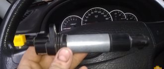
- Wear a glove or take a dry cloth.
- Remove the power wires from the module sockets one by one.
Each removed wire must be brought to the power unit block. Without touching, a spark should discharge from the tip. A blue spark and a discharge accompanied by a crackling sound will indicate the necessary supply of discharge current. In this case, the engine should respond to the removed working wire by reducing the speed. If a wire is detected from which the spark does not come or it is quite weak, the engine speed will not change.
The previously described error codes from the on-board computer can also help in finding the wire with no spark.
For more effective testing, it is necessary to dismantle the ignition distribution device and carry out a test with a tester. This is easy to do if you follow these instructions.
First you need to dismantle the device. This is done as follows:
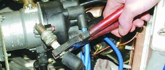
- Disconnect the ground terminal from the battery.
- Remove 4 high-voltage wires from the MZ sockets.
- Disconnect the electrical power plug.
- Unscrew the 3 nuts securing the module.
- Remove the device.
Next, a mandatory visual inspection of the device is carried out. The ignition module is a rather fragile device. The presence of defects on the housing, cracks and dents, can cause an internal short circuit. You also need to pay attention to the sockets for power cables. There should be no oxidation or dirt on the terminals. Any malfunctions should be eliminated by cleaning with a solvent. Next you need to check the connecting plug. Its contacts also need to be cleaned. Below is a step-by-step guide on how to check the VAZ-2114 ignition module with a multimeter.
Checking the connecting plug
First you need to check the incoming voltage to the module. This is done as follows:
- The multimeter is switched to voltmeter mode to measure DC voltage.
- The red measuring probe is connected to the incoming half of the module plug, with the central contact. It is he who is responsible for powering the device.
- The black test probe is connected to ground.
- Turn on the ignition.
The tester should show a voltage of 11.5–14 volts, equal to the battery charge.
Next, the incoming signal is checked. The voltmeter remains in the same position.
- The red probe of the tester is connected to contact “1” of the coming side of the plug. This contact is responsible for the distribution of pulse current for the cycle of candles 1–4.
- The black probe connects to ground.
- It is necessary to crank the starter a few turns.
The voltmeter should show pulse voltage. Contact “3” on the plug is checked in the same way.
Module plug
For this test, you need to switch the multimeter to resistance measurement mode. Next you need:
- Connect the red control probe to terminal “1”.
- Connect the black control probe to terminal “3”.
- The operating resistance should be within 0.5 Ohm.
In this way, both secondary windings of the ignition coils are checked. Any deviations in resistance will indicate an internal violation of the integrity of the winding.
Using the following test, the presence or absence of a short circuit is checked.
- The multimeter remains in resistance measurement mode.
- Connect the red test probe to the central contact of the plug.
- Connect the black test probe to the device body.
- The tester should not show any results. This will indicate that there is no internal short circuit. Any minimal resistance during this test is reason to replace the module.
The following check is needed to test the primary windings. The check is carried out as follows:
- The multimeter is switched to resistance measurement mode.
- Insert the red measuring probe into the “1” socket for high-voltage wires.
- Insert the black measuring probe into socket “4”.
- The operating resistance of the primary phase windings is 0.5 Ohm. Any data that differs from the nominal value can be recognized as the presence of an interturn short circuit in the primary winding of cylinders 1–4.
The test of sockets “2” and “3” is carried out in a similar way. Their operating resistance should also be 0.5 Ohm.
Additionally, you can check in the same way, but between sockets “1” and “2”. There are no internal connections between them. If there is resistance, the part is considered unsuitable for further use.
Why does the MH fail?
The cause of failure of the ignition module is aging and insulation breakdown. Most often, the MZ fails along a vein of broken high-voltage wires, which causes a spark from the module to hit the housing, thereby exposing it to excessive currents.
Old spark plugs have high resistance due to carbon deposits, which can cause a breakdown in the housing, which leads to failure of the ignition module.
You should change spark plugs every 30-40 thousand kilometers, and also inspect high-voltage wires for breakdown.
Other reasons
If, after checking the ignition module of an injection-type VAZ-2114 car, no malfunction was identified, then you should pay attention to breakdowns or improper operation of adjacent devices.
- Powertrain control unit. It happens that after an electrical short circuit, the ECU loses its internal settings. To restore functionality, you need to disconnect the “+” terminal from the battery and connect it again. The ECU will enter a temporary reboot, and the module's operation may be restored. It is also worth carrying out professional diagnostics of the on-board network.
- Crankshaft position sensor. An important source of pulse signals. Its data affects the distribution of voltage from the ECU to secondary devices. It is necessary to check the functionality of this element, its wiring, and the protective fuse. If necessary, replace faulty parts.
- Hall Sensor. This device is responsible for the distribution of pulses. Signals are generated due to contact connection during rotation of the device rod. Any deviations in the supply of signals affect the operation of the ignition module.
- Generator. The high charge current of this mechanism often leads to complete burnout of the secondary winding of the MC. The first problem may be a faulty fuse. If such a problem is detected, it is worth checking the amount of voltage coming from the generator.
The system, which includes a Hall sensor, DPKV and ignition module, works by calculating the position of the crankshaft. This is how the exact order of the spark cycle on the cylinders is achieved.
Important! Very often, the performance of the MH is affected by careless operation of this device. The cause of failure may be:
- Lack of contact with the “mass”. This occurs when the 3 bolts securing the device are insufficiently tensioned. Periodic loss of contact leads to a break in the circuit. The newly appeared contact causes the discharge of a current of greater strength. This leads to internal burnout of the secondary winding of the coils.
- Lack of contact on spark plug caps. A poor connection leads to contact vibration, often high-voltage wires fly out and short to ground. This leads to damage to the MZ discharge contactor.
- Poor contact or oxidation at the battery terminals. It also leads to a short-term but powerful discharge of the primary winding.
- Spark plug gap. The manufacturer sets a fixed spark plug gap. The maximum value for spark plugs installed on injection engines can be 1.3 mm. A large gap leads to a spark hitting the housing. The spark is simply deflected to the side. A small gap size can lead to breakdown of high-voltage wires or the ignition coil itself. The high voltage pulse current is simply discharged back into the circuit.
Many car enthusiasts try to disassemble and repair ignition modules themselves. With proper knowledge of electronics, only the discharge regulator can be repaired. The coils will have to be rewound. But the main difficulty lies in the subsequent sealing and insulation of the inductors. Any remaining cracks will cause breakdown and failure. It is better to purchase and replace the MZ with an exact analogue.
How to check the ignition coil of a VAZ
If the ignition coil is faulty, the engine will not start. A characteristic sign of a faulty coil is its increased temperature when the ignition is turned off. This is easy to determine by touch.
Signs of a faulty ignition module may include the following:
- hesitant engine starting or failure to start;
- failures during sudden changes in speed;
- high fuel consumption;
- two cylinders do not work, the engine is feverish;
- lack of dynamics;
- a sharp drop in power;
- drop in power and thrust after warming up.
These symptoms may not only be caused by the ignition module. To determine the malfunction, it is enough to spend a few minutes diagnosing spark plugs, high-voltage wires and caps. This will eliminate the remaining elements of the ignition system and make sure that it is the ignition module that is faulty.
Design
The design of the ignition module is quite complex, since it combines technology and electrics. The device serves to create high voltage transmitted to the spark plugs. It is this supplied current that is the basis for ignition.
The operation of the module ensures fuel combustion and, accordingly, engine operation. In very simple terms, the car won’t go anywhere without the module.
We recommend: All about the oil in the gearbox of a Gazelle car
For VAZ models, the use of two types of ignition modules is provided:
- Separate;
- Block.
Block ones differ in that the coils operate one per pair of spark plugs. These are the devices that are installed on the “fourteenth” model of the domestic automaker.
The coil distributes power to two candles at once, and its design includes the following elements:
- High voltage wires;
- Low voltage terminals;
- Secondary and primary winding;
- Core.
Separate modules, where the coils supply a separate circuit to each of the 4 sections, are distinguished by the output of high-voltage wires through a spring contact. Block ones are easier to check, they are easy to remove and return to their place.
It is noteworthy that with a size of 11x11x7 centimeters, this block weighs about 1.5 kilograms.