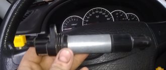
The ignition switch in cars of the VAZ family fails from time to time due to weakening of the contact posts or burning of the contacts inside it. It also happens that the cams of a plastic roller are produced. You can disassemble the lock and clean it, but it’s better to just replace it with a new one, considering that it costs pennies compared to imported locks.
But if connecting the wires together did not result in the starter operating (or it did not turn on the first time), check the solenoid relay on the starter. The contact spots on it may also burn out, which will prevent the circuit from closing normally. Alternatively, you can use a screwdriver to short-circuit the two large terminals on the solenoid relay (before doing this, put the car in neutral and use the handbrake). When closed, the starter should begin to spin vigorously. If this happens, remove and change the solenoid relay. If the starter rotates “sluggishly” when it closes, you will have to remove it and check the condition of the brushes.
All operations are performed with your own hands, without the help of car service specialists. Moreover, the price of an ignition switch on a VAZ2106 is up to 100 rubles. To replace it, you will need to know the pinout of the wires coming from it, for which the editors of the site 2 Schemes.ru have prepared a large reference material.
The ignition switch is designed not only to start the engine - it performs several functions at once:
- supplies voltage to the vehicle’s on-board network, closing the circuits of the ignition system, lighting, sound alarm, additional devices and instruments;
- at the driver’s command, turns on the starter to start the power plant and turns it off;
- turns off the power to the on-board circuit, preserving the battery charge;
- protects the car from theft by fixing the steering shaft.
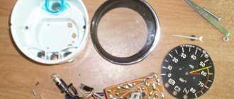
This option is for those who want to illuminate the BSK block without plexiglass
We erase the front plate with a stationery knife.
Print out the same drawing again, but on matte paper.
It goes something like this
Then I made holes in the case with a soldering iron.
To diffuse the light, I inserted pieces of transparent plastic into these holes (cut from a simple CD box) and made one side matte with a knife, but better with sandpaper
Now we are illuminating the Vase, which I forgot to photograph.
To illuminate the BSK module, I took a diode strip (2 pieces from it)
There are no pictures, so I took approximately the same module as a base and added LED strips there. I think the meaning is clear.
The strips need to be glued between the door LEDs
I soldered the backlight wires to pins 1(+) and 3(-) to these
Now the drawn car on the block will glow brightly when the ignition is on.
In order for the car to not glow so brightly, I soldered a 620 Ohm resistor to the positive wire.
Errors when connecting/operating the on-board computer
Error: “No connection with the controller” or “break in the K-line.”
It indicates that the K-line is not connected or a contact break has occurred. Check the wire according to the diagram described above. Most likely, the contact has come off the diagnostic block.
Error: Incorrect temperature sensor readings.
If, according to the instrument readings, your temperature outside is -40, then this indicates that a wire has broken or there is no such analyzer at all. If the sensor shows -25, but it's only -10 outside, then you need to replace it.
Instrument panel VAZ 2110 - description of lamps and indicators
Designations of indicator lamps on the instrument panel of VAZ 2110 - 15.
Many car enthusiasts are faced with this seemingly simple question. What do the indicator lights on the instrument panel mean?
And what do we know, they all light up together only when the ignition is turned on, and when one of them lights up while driving, it becomes a little uneasy.
I didn’t know this myself when I switched to the “two” after the “seven”; on the 2107, half of them didn’t light up at all, so I didn’t know what it was and what it was for. And a friend of mine, after buying a car in Novorossiysk, even bought a whole book on VAZ, due to ignorance of these light bulbs.
The symbols on the instrument panels on all VAZs are almost the same, just the location is different.
Let's start in order.
1 — Coolant temperature, in degrees Celsius.
2 — Tachometer, engine speed.
5 — Speedometer, vehicle speed in km/h.
6 - Fuel level in the tank. When there are 5-7 liters left, a yellow light comes on - a warning or an icon with a picture of a gas station.
7 - Actually, this is an image of a gas station, signaling the need to refuel.
8 - Indicator lamp for turning on the dimensions.
9 — The brake fluid level is low, it may be leaking somewhere.
10 - Turn on the high beam.
11 - Clock adjustment knob (hours/minutes - switches when pressed), sometimes this knob serves as the function of switching the total mileage/day mileage (on panels with a narrow display).
12 — The display showing the total mileage/daily mileage is narrow on some models.
13 - Hazard warning lamp - “hazard light”.
14 - Check Engine, often indicated by this icon
- this means a malfunction in the engine, it is recommended to stop the engine.
15 — Display with a clock (can show the outside air temperature if there is a temperature sensor).
16 - Malfunction in the battery charging system: loose or broken generator belt, generator malfunction, open circuit and other problems.
17 - Parking brake indicator.
18 - Insufficient oil pressure in the engine, it is recommended to turn off the engine and find the cause.
19 — Air damper light (on carburetor engines)
I’ll also add about the lamps on the additional panel in the dashboard of the VAZ 2110 - 12.
— The light marked with an arrow indicates a malfunction of the parking lights or brake lights. — Below is a brake pad wear indicator, if it lights up, check the brake pads, maybe it’s time to change them. — Seat belt warning light — this is clear from the picture.
On the other side from above:
— Low engine oil level — Low washer fluid level — Increased coolant temperature
This is how the review turned out. If some light comes on and the signal beeps, do not panic. Usually it's little things.
Save this note to yourself on your social network by clicking on one of the buttons below.
Peculiarities
VAZ 2114 cars have many innovations compared to 2109, in particular, this concerns electrical wiring.
Whether it is an injector or a carburetor, the wiring diagram for the VAZ 2114 is located in:
- vehicle interior;
- in the engine compartment;
- behind the car body.
It should be noted that carburetor VAZ 2114 were produced only from 1997 to 2000, then they were equipped with carburetors from the VAZ 2108.
But new engines have a more powerful ignition system; accordingly, the electrical control circuit is also characterized by certain features, for example:
- There is a new harness for connecting to the ignition module terminal. This component sends signals to the spark plugs through high-voltage wires.
- Another harness was added to allow mounting of the switch.
- Additional wiring has appeared to connect the adsorber valve to the injection system controller.
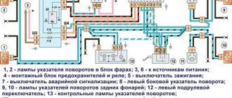
Wiring and equipment diagram 2114
Many VAZ 2114 car owners mistakenly believe that thanks to the ignition module, they don’t have to use a coil. In fact, this device is equipped with two coils and two switches. One of the coils transmits the signal to the first and fourth cylinders, and the second - to the second and third.
The equipment system of VAZ 2114 cars with an injector engine has undergone certain innovations not only due to the addition of new electrical equipment, but also as a result of modernization of the car as a whole:
- it is possible to install a heated side mirror device;
- you can connect the front seat heating system;
- VAZ 2114 car owners can install PTF, etc.
display unit for on-board control system of VAZ 2110 cars | VAZ 2111 | VAZ 2112
Rice.
1-8, on-board control system display unit The on-board control system display unit (Fig. 1-8) informs about the state of components and systems of the VAZ 2110, VAZ 2111, VAZ 2112 vehicle through signaling devices. 1 — the indicator of insufficient oil level in the engine crankcase lights up in orange when the oil level in the engine crankcase drops below the “MIN” mark of the indicator. Before adding oil, check whether there is any oil leakage due to loss of tightness of the lubrication system. 2 - the left front door ajar indicator lights up red when the left front door is not closed. 3 — the right front door ajar indicator lights up red when the right front door is not closed. 4 - the brake light and side light bulb malfunction indicator lights up orange if one of the brake light bulbs or side lights is faulty. 5 — the front brake pad wear indicator lights up orange if the thickness of the linings has decreased to 1.5 mm. 6 - the seat belt warning light lights up red when the driver is not fastening his seat belts. 7 — the right rear door ajar indicator lights up red when the right rear door is not closed. 8 - the left rear door ajar indicator lights up red when the left rear door is not closed. 9 - the indicator of insufficient coolant level in the expansion tank lights up orange when the coolant level in the expansion tank on a cold engine drops below the permissible limit. Before adding fluid to the expansion tank, check the tightness of the cooling system. 10 - the indicator of insufficient washer fluid level in the tank lights up in orange if there is less than 1 liter of washer fluid left in the tank. The display unit of the on-board control system of VAZ 2110, VAZ 2111, VAZ 2112 vehicles can be in the following modes: off; Standby mode; pre-departure monitoring of signaling devices; parameter control. The display unit of the on-board control system of the car VAZ 2110, VAZ 2111, VAZ 2112 is in the “Off” mode if the key is not inserted into the ignition switch. In position 0 (“Off”) of the key in the ignition switch, the display unit of the on-board control system goes into “Standby Mode”. If the driver’s door is opened, the “Forgotten key in the ignition switch” malfunction will occur and the on-board control system display unit will sound for 5-10 seconds. will give an intermittent signal. The signal can be interrupted either by closing the door, or by removing the key, or by turning the key in the ignition switch to position I (“Ignition”). In position I of the key in the ignition switch, the display unit of the on-board control system of the VAZ 2110, VAZ 2111, VAZ 2112 vehicles switches to the “Pre-departure control of alarms” mode, in which to check their serviceability for 2-6 seconds. all light and sound indicators turn on, and then after a pause of 1 second, the display unit of the on-board control system switches to the “Parameter Monitoring” mode and, if there is a malfunction, generates an alarm according to the following algorithm: the indicator light for the parameter that is outside the normal range begins to flash for 5-10 seconds, after which it switches to a constant glow mode until the malfunction is eliminated or the key in the ignition switch returns to position 0 (“Off”); simultaneously with the light indicator for 5-10 seconds. the sound alarm turns on; If at the same time another malfunction occurs, then the sound alarm and light alarm in the blinking mode begin to work for the last malfunction, as a higher priority, and the light indicator of the previous malfunction goes into constant light mode.
When using site materials, an active link to car-exotic.com is required!
Standard connection tw 9010
The Tomahawk equipment manufacturer suggests connecting the alarm as follows:
Reviews tell us that the standard connection option in VAZ cars is easy to implement. You don’t have to connect the hood switch, the Anti-Hijack button, and the “blue-red” wire coming from the connector is definitely not needed. You can connect a blocking relay connected to the “black-yellow” cable if autostart is needed. In general, connecting the Tomahawk tw 9010 signaling system is a pleasure if we are talking about a VAZ-2110.
There are two connectors under the dashboard of the VAZ 10s. They are painted white and red. When making T-shaped connections, the following wires are pulled from the connectors:
- Tachometer cord connected to pin “3” of the white connector;
- Parking brake sensor wire (white connector);
- Two cords from the turn signal lamps (terminals 5 and 6 of the red connector).
All Tomahawk car alarm systems allow the starter to be disabled. If the owner needs this option, then a relay is connected to the break in the “50P” cord.
Blocking using an “external relay” is a standard option for the Tomahawk tw 9010 alarm, unlike the tz 9030 systems.
If you do not need interlocking, still connect the “yellow” cord of the 6-pin connector to the “15GCH” terminal.
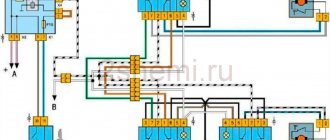
Pinout of 2110 instrument panel connectors
Statistics
Users: 16321 Articles: 252 Links: 2 Content views: 2314496
| Administrator | |||
| 17.01.2011 12:12 | |||
| 1 | Housing (weight) | 1 | * External air temperature sensor |
| 2 | Tachometer (low voltage input from ECU) | 2 | Fuse F19 + 12V power supply |
| 3 | Tachometer (high voltage input from coil) | 3 | Housing (weight) |
| 4 | Const +12V from battery (via 6th fuse) | 4 | Instrument lighting switch |
| 5 | Coolant temperature sensor. | 5 | Turn signal RIGHT |
| 6 | Fuse F1 (side light) | 6 | Turn signal LEFT |
| 7 | Throttle valve (“choke”) | 7 | Brake fluid level |
| 8 | Check Engine Light | 8 | To the trip computer |
| 9 | Fuse F19 + 12V power supply | 9 | Speed sensor |
| 10 | Fuse F19 + 12V power supply | 10 | Terminal "T" fuel gauge |
| 11 | Parking brake, terminal “VK” | 11 | Fuse F3 (high beam) |
| 12 | Generator output "D" | 12 | Hazard switch |
| 13 | Oil pressure sensor | 13 | To terminal “50” of the ignition switch |
* - in relation to two-window panels VDO and Schetmash. An external ambient temperature sensor is installed. It is attached under the bumper. Not used on single-window versions. On panels with a mechanical odometer, this contact receives a signal from the “W” terminal of the fuel level sensor.
Color coding of wiring of various panels.
| Connecting wires to the VDO panel | |||||||
| White block | Red block | ||||||
| 1 - Black | 1 - Blue-red | ||||||
| 8 | White-red | 2 | Brown-red | 8 | Brown | 2 | Orange |
| 9 | 2 orange | 3 | Yellow | 9 | Grey | 3 | 2 black |
| 10 | 2 orange | 4 | Red-blue | 10 | Pink | 4 | White |
| 11 | 2 brown-blue | 5 | Green-white | 11 | 2 Green-black | 5 | Blue |
| 12 | Brown-white | 6 | Yellow-black | 12 | Blue-white | 6 | Blue-black |
| 13 | Gray blue | 7 | — | 13 | White | 7 | Pink blue |
| Connecting wires to the “Schetmash” panel, Kursk | |||||||
| White block | Red block | ||||||
| 1 - Black | 1- Blue-red | ||||||
| 8 | White-red | 2 | Brown-red | 8 | Brown | 2 | Orange |
| 9 | Blue | 3 | Yellow | 9 | Gray+yellow | 3 | Black |
| 10 | Orange | 4 | White-red | 10 | Pink | 4 | White |
| 11 | Brown blue | 5 | Green-white | 11 | Green-black | 5 | 2 blue |
| 12 | Brown-white | 6 | 2 Brown | 12 | — | 6 | 2 blue-black |
| 13 | Gray blue | 7 | — | 13 | Red | 7 | Pink blue |
| Connecting wires to the AP panel, Vladimir | |||||||
| White block | Red block | ||||||
| 1 - Black | 1- blue-red | ||||||
| 8 | White-red | 2 | Brown-red | 8 | Brown | 2 | Orange |
| 9 | 2 orange | 3 | Yellow | 9 | Grey | 3 | 2 Black |
| 10 | 2 orange | 4 | Red-blue | 10 | Pink | 4 | White |
| 11 | 2 brown-blue | 5 | Green-white | 11 | 2 Green-black | 5 | Blue |
| 12 | Brown-white | 6 | Yellow-black | 12 | Blue-white | 6 | Blue-black |
| 13 | Gray blue | 7 | — | 13 | Red | 7 | Pink blue |
| Connecting the trip computer | |
| 1 | Green. From KSUD (ECU) - fuel consumption signal |
| 2 | Orange - terminal “15” of the ignition switch |
| 3 | White-red - terminal “30” of the ignition switch |
| 4 | Black - Common wire (Ground) |
| 5 | Brown - Speed Sensor |
| 6 | ——- |
| 7 | Green-red - “+” fuel consumption sensor |
| 8 | White - to the instrument lighting control |
| 9 | ——- |
Car radio connection options
The main elements, in addition to the device itself, are the connectors. They are:
- The international standard is ISO connectors.
Advice: ISO standard plugs must not be used for purposes other than their intended purpose. This may lead to equipment failure.
- Individual. In this case, you can buy an adapter for the ISO connector or cut the wires from the radio plugs and the car wiring, then connect the car radio according to the color wiring of the device. You can use electrical tape for winding. But besides the fact that this method of installing a car radio is not aesthetically pleasing, it is not always reliable. The connection of the wires does not guarantee a tight fit and sticking of electrical tape on the wires, especially in winter, which can lead to a short circuit.
Advice: This method can be done, as a last resort, taking precautions and using heat-shrinkable tubes.
It is enough to install ISO standard connectors once and you no longer need to think about how to connect a pioneer car radio. You will need to pull out the old device along the slide and switch the plugs from the old product to the new one, which is then put in place. The photo shows ISO standard plugs.
ISO plugs
ISO standards for connecting car radios
There are some features and different colors of plugs that you need to use to properly connect your pioneer car radio. There are two plugs as standard:
- Black. Through it, the device is powered and its additional functions are provided.
- Brown. Provides output to the car's acoustics for a sound signal.
When connecting the radio, the positive wire must be connected correctly.
Tip: When connecting the device, it is better to take the positive wire through the fuse directly from the battery. The diameter of the wiring should not be less than the diameter at the car radio connector. Sometimes you can connect from the cigarette lighter.
To reduce leakage, the following connection diagram for a pioneer car radio can be used:
Car radio connection diagram to reduce leakage
- Black color is earth.
- Yellow – power supply from the battery (+12 volts).
- Red – signal from the ignition switch to turn on the radio (+12 volts).
- Blue – antenna is turned on (+12 volts when the device is turned on).
- Diodes are different, maybe low-current type KD522B.
After installing the pioneer car radio, it is connected by applying a plus to two wires: yellow and red:
- The yellow wire carries out settings and is responsible for powering the product’s memory.
- Red is power and turns off the radio.
The instructions indicate that the red wire should be connected through the ignition switch, which will ensure that the device turns off after the ignition is turned off.
Pinout of VAZ Bosch ECU connectors
Bosch 7.9.7 January 7.2
| Number | Bosch M1.5.4 (1411020 and 1411020-70) January 5.1.1 (71) | Bosch M1.5.4 (40/60) January-5.1 (41/61) January 5.1.2 (71) | Bosch MP7.0 |
| 1 | Ignition 1-4 cylinders. | Ignition 1-4 cylinders. | Ignition 1-4 cylinders. |
| 2 | . | Ground ignition wire. | . |
| 3 | Fuel pump relay | Fuel pump relay | Fuel pump relay |
| 4 | Stepper motor PXX(A) | Stepper motor PXX(A) | Stepper motor PXX(A) |
| 5 | Canister purge valve. | Canister purge valve. | |
| 6 | Cooling fan relay | Cooling fan relay | Left fan relay (only on Nivas) |
| 7 | Air flow sensor input signal | Air flow sensor input signal | Air flow sensor input signal |
| 8 | . | Phase sensor input signal | Phase sensor input signal |
| 9 | Speed sensor | Speed sensor | Speed sensor |
| 10 | . | General. Oxygen sensor weight | Oxygen sensor weight |
| 11 | Knock sensor | Knock sensor | Knock sensor input 1 |
| 12 | Power supply for sensors. +5 | Power supply for sensors. +5 | Power supply for sensors. +5 |
| 13 | L-line | L-line | L-line |
| 14 | Weight of injectors | Weight of injectors | Weight of injectors. Power "ground" |
| 15 | Control of injectors 1-4 | Oxygen sensor heater | Check Engine Light |
| 16 | . | Injector 2 | Injector 3 |
| 17 | . | Recirculation valve | Injector 1 |
| 18 | Power supply +12V non-switchable | Power supply +12V non-switchable | Power supply +12V non-switchable |
| 19 | Common wire. Weight of electronics | Common wire. Weight of electronics | Common wire. Weight of electronics |
| 20 | Ignition 2-3 cylinders | Ignition 2-3 cylinders | |
| 21 | Stepper motor PXX(C) | Stepper motor PXX(C) | Ignition 2-3 cylinders |
| 22 | Check Engine Light | Check Engine Light | Stepper motor PXX(B) |
| 23 | . | Injector 1 | Air conditioner relay |
| 24 | Stepper motor weight | Weight of stepper motor output stages | Power grounding |
| 25 | Air conditioner relay | Air conditioner relay | . |
| 26 | Stepper motor PXX(B) | Stepper motor PXX(B) | Weight of sensors TPS, DTOZH, DMR |
| 27 | Ignition switch terminal 15 | Ignition switch terminal 15 | Ignition switch terminal 15 |
| 28 | . | Oxygen sensor input | Oxygen sensor input |
| 29 | Stepper motor PXX(D) | Stepper motor PXX(D) | Oxygen sensor 2 input signal |
| 30 | Weight of sensors MAF, DTOZH, DPS, DD, DPKV | Weight of sensors MAF, DTOZH, DPS, DD, DPKV | Knock sensor input 2 |
| 31 | . | Reserve output high current | Rough road sensor input signal |
| 32 | . | . | Fuel consumption signal |
| 33 | Control of injectors 2-3 | Oxygen sensor heater. | . |
| 34 | . | Injector 4 | Injector 4 |
| 35 | . | Injector 3 | Injector 2 |
| 36 | . | Exit. Intake pipe length control valve. | Main relay |
| 37 | Nutrition. +12V after the main relay | Nutrition. +12V after the main relay | Nutrition. +12V after the main relay |
| 38 | . | Low-current backup output | . |
| 39 | . | . | Stepper motor IAC (C) |
| 40 | . | Reserve input discrete high | . |
| 41 | Request to turn on the air conditioner | Request to turn on the air conditioner | Oxygen sensor heater 2 |
| 42 | . | Reserve input discrete low | . |
| 43 | Signal to tachometer | Signal to tachometer | Signal to tachometer |
| 44 | CO - potentiometer | Air temperature sensor | . |
| 45 | Coolant temperature sensor | Coolant temperature sensor | Coolant temperature sensor |
| 46 | Main relay | Main relay | Cooling fan relay |
| 47 | Programming permission | Programming permission | Air conditioner request signal input |
| 48 | Crankshaft position sensor. Low level | Crankshaft position sensor. Low level | Crankshaft position sensor. Low level |
| 49 | Crankshaft position sensor.High level | Crankshaft position sensor.High level | Crankshaft position sensor.High level |
| 50 | . | Recirculation valve position sensor | Programming permission |
| 51 | . | Request to turn on the power steering | DC heater |
| 52 | . | Reserve input discrete low | . |
| 53 | Throttle position sensor | Throttle position sensor | Throttle position sensor |
| 54 | Fuel consumption signal | Fuel consumption signal | Stepper motor IAC (D) |
| 55 | K-line | K-line | K-line |
Useful: VAZ ignition switch pinout
Ignition switch malfunctions
The ignition switch on a VAZ 2110 must be replaced if its operation cannot be restored in any way or the key is broken/lost. In other cases, they are usually repaired.
There are two groups of main breakdowns:
- The mechanics are faulty . The most common problem is the breakage of the larva. The keys are made of soft metal, so they are unreliable and can often simply break off. There is also a problem with the steering wheel locking or the key may simply get stuck when in the on position.
- Wear of the contact group . No matter what kind of damage you have, you will still have to dismantle the lock. If the tongue of the blocker is jammed, you will have to work hard to correct the situation. The contact group or larva is quite easy to repair.
In order to check the ignition switch on a VAZ 2110, there are many instructions and methods, we will consider some of them.
Detailed instructions for checking faults in the ignition switch:
- The first thing to do is disconnect the wire from the negative terminal of the battery.
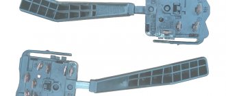
- Remove the plastic cover of the steering column to get to the contacts of the pads, because it is with their help that power is connected to the car's electrical wiring. Next, disconnect the connector of the harness itself from the on-board network and pull it out.
Indication symbols
As you know, all the lights on the control panel come on when the ignition is turned on, and then, when the engine is already running, most of them go out. But when one remains on or blinks, this cannot but be alarming, because not everyone can immediately figure out what malfunctions this indicates, which of the systems needs urgent repairs.
Let's look at the designations of the instrument panel of the VAZ 2110. You should know that regardless of whether the panel is new or old on your car, the designations are almost the same, but the indicators may be located slightly differently.