Let us remind you that the emergency signaling is carried out by the same electrical circuit that turns on the direction indicators. Therefore, it is possible that problems in the electrical circuit will be similar. But before we start talking about malfunctions, let’s remember what the electrical circuit of the alarm on the VAZ 2114 looks like and how it turns on. Also from the same article, the reader will learn how to move the emergency button from under the steering wheel to the dashboard and install an elegant Euro button.
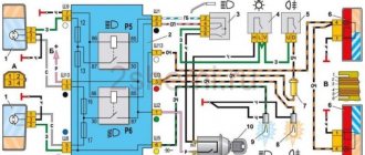
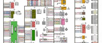
Emergency gang diagram for VAZ 2114
Electric current from the power source (3) enters the mounting block (4), where it passes through two fuses and a relay to buses 2 and 4 through the X11 chip of the mounting block. From the mounting block, the wires go to the ignition switch and hazard warning switch, which has several modes. There is another turn signal switch in the electrical circuit, which is called the left steering column switch (12). The turn signal headlights in the diagram are indicated by numbers:
- 1,2 – front,
- 8, 11 – side,
- 9.10 – rear.
Useful: Where
To complete the picture, we provide, as an illustration, a diagram of the location of fuses and relays in the mounting block.
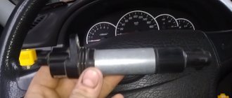
How to use the ignition switch
Any alarm equipped with auto-start is usually equipped with 5 power terminals:
Cord 3 here is the control one; it is connected to the starter terminal. And on the blue wire, that is, on terminal 15/2, the voltage may disappear when the starter is running, or it may remain on it all the time. When setting up, select one option.
VAZ 2101-2107 cars have their own characteristics. The coil of the additional relay shown in the diagram cannot be connected to the ignition cord going to the standard relay. The line is simply not designed for additional load!
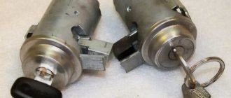
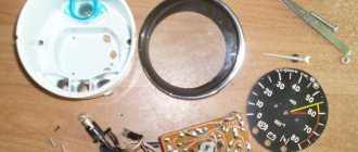
Let's see what the ignition switch looks like in reality:
If you really need autostart, the starter cord (red) will have to be cut. Let's list what the correspondence between the lock and alarm cords looks like. The alarm cable will be indicated on the left:
- Green – free;
- Blue – free;
- Red – pink;
- Black-yellow thick – red (tap to starter);
- Black-yellow thin – red (bend to the lock);
- Yellow - blue thick.
In theory, everything turns out simple.
Of course, you can install the autostart system yourself. But it is better to entrust this task to a professional electrician. The three cords leading to the alarm must carry significant current. In new VAZ models the number of these cords will be no less.
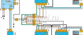
Connection diagram for Euro button on VAZ 2114
The figure shows a diagram of connecting turn signals and emergency lights with a new Euro button.
The location of the original emergency button caused a lot of complaints from car owners.
The AvtoVAZ emergency flasher has another significant drawback - its tendency to stick. That is, you turn it on, but how to turn it off is a problem. You have to arm yourself with tools, remove the button from under the steering wheel and fix the loose fastener. This is what causes the sticking.
Useful : The emergency lights and turn signals on the VAZ 2114 do not work
Fortunately, the same engineers provided one slot for a button on the dashboard. Obviously, they left this slot for installing additional equipment in case the car owner wants to modernize the interior, or do tuning in it, and add some cutting-edge device. For now, this nest is closed with a plug (pseudo-button). Almost all car owners bring their emergency lights here, since pressing on them here is much more convenient than somewhere under the steering wheel.
At the beginning of the section there is a diagram of the VAZ 2114 emergency gang, according to which the Euro button will be redone. First, at the nearest car market or in an online store that sells spare parts, we find the Euro button.
You will also need a four-pin relay with a connector (with a block). First, the old button must be dismantled and the wires removed from it. We won't need it anymore. And the wires with contacts will still serve. For ease of connection, the wires can be labeled. Below is a diagram for connecting an emergency light on a VAZ 2114. The diagram shows how to move the wires from the old button to the new one and connect a four-pin relay.
In accordance with the diagram of the emergency signal button on the VAZ 2114, the wires are transferred to the new button and connected to a four-pin relay.
You will get a kind of garland of wiring and devices. This garland is to be mounted in the dashboard of the car. The chip from the old button is removed and the ends of the garland are inserted into its connectors.
If everything was done correctly, the button will work. Now you have to insert the button in place of the plug and remove the wires under the dashboard. By the way, the minus is taken from the minus of the on-board computer. To insert the emergency signal chip into its place, the wires will have to be disconnected for a while. The wiring harness runs from the steering column under the on-board computer. To do this, you will have to remove the corresponding casings and shields. Then the wire terminals are inserted into the connectors again. accidents
What to do with the hole from the old button? Car owners solve this problem in different ways. Some people find a casing of the appropriate size, but without a hole for the button, while others install a plug that matches the color of the casing. On the euro button itself there is a red indicator light, by which you can understand that the emergency lights are on. In addition, when the emergency lights are on, both turn signal arrows on the dashboard flash. The network offers other options for installing the Euro button. For example, with connecting diodes. But in this case, the turn signals light up when the ignition is off, which is not very convenient. The basis is this wiring diagram for the Euro emergency flasher button of the VAZ 2114
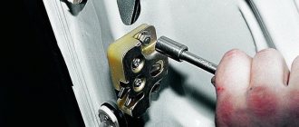
To get to the standard button, remove the casing. We take out the old button, its upper part can be thrown away, the spring is not needed. The lower part remains. Through the side wall removed from the driver's side, we pull out the chip with wires under the on-board computer. Here, too, the partition is removed. The wires are soldered in the following order:
- We connect contacts 4 and 8 through an additional wiring;
- The cathodes from the diodes are connected to contacts “1” and “3” by soldering, and the anodes are soldered together;
- The wires of the Euro button with contacts “D” and “2” are connected by soldering to the free anodes of the diodes.
- There is an indicator on the Euro button, but the light bulb is not inserted into the dashboard. It is necessary to insert the light bulb and connect wire 2 to the dashboard;
- The wire of contact “1” on the button is connected to wire 7 on the wiring harness;
- Contacts “A” and “B” are routed to ground and backlight, respectively. To do this, the terminals with wiring must be soldered to contacts A and “B”.
- The resulting wiring harness is connected to the supply line.
To ensure reliable soldering, the contact surfaces are treated with LTI-120 soldering flux;
Design and principle of operation of an electromagnetic-thermal turn relay
Relays of this type do not have a very complicated design. It is based on an electromagnetic relay of a traditional design - a cylindrical core with a winding of thin copper wire. At the top of the core there are two contact groups, and on the sides there are flexible metal anchors (or, as they are called, anchors). One contact group is designed to close the circuit of the turn signal indicator lamp located on the dashboard. And the second contact group directly closes the circuits of the direction indicator lamps, and it is its design features that ensure the blinking of the turn signals.
The armature of the contact group of the turn signal lamps is pulled away from the contact located on the core using a thin nichrome string, so in the normal position the turn signal circuit is open. The opposite end of the string is fixed on a platform made of insulating material, which serves as the basis for installing the core. The nichrome string is connected through a resistor to the turn signal switch circuit, so current flows through it during operation of the relay.
This entire structure is placed in a cylindrical metal case; the bottom of the case is a platform made of insulating material with a relay. At the bottom of the platform there are contacts with the help of which the breaker relay is connected to the turn signal circuit.
The operation of an electromagnetic-thermal relay is quite simple and boils down to the following. When the turn signal is turned on, a circuit is closed that includes the turn signal lamps, a resistor, a relay winding and a nichrome string. Due to the resistance of the resistor, the voltage supplied to the lamps is low, so their filaments burn at full heat. Nichrome, as is known, has a high resistivity and heats up greatly when current flows - thanks to this heating, the nichrome string increases its length, and the armature pulled by it, under the influence of the attraction of the core, straightens and at some point closes the contact group. As a result, current begins to flow bypassing the resistor and the nichrome string, and the turn signal lamps light up in full force.
However, stopping the heating of the string leads to its cooling and shortening, and the armature is again pulled away from the core, opening the contacts - the turn signal lamps go out, and the cycle repeats again. The heating and cooling of the nichrome string occurs quickly, so the lamps blink at a frequency ranging from 60 to 120 times per minute.
The current position of the contact group of the direction indicator lamps (let's call it the first) is associated with the work of the contact group of the signal lamp (let's call it the second). When the contacts of the first group are open, current flows through the winding, but it is not enough to attract the armature of the second group, so the signal lamp does not light up. When the string is pulled and the first contact group is closed, the current flowing through the winding increases sharply, and it is already sufficient to attract the armature of the second contact group. As a result, simultaneously with the blinking of the direction indicators, the warning light on the dashboard also blinks.
Characteristic clicks during operation of the direction indicators occur due to the impact of the anchors on the contacts when they are closed and opened. Clicking is a characteristic feature of electromagnetic relays, and it comes in very handy in breakers.
The electromagnetic-thermal relay has a simple design, and this is its main advantage. But this type of relay has many more disadvantages: over time, the string is stretched, as a result of which the relay stops functioning normally, during operation the relay heats up, which changes its characteristics, and if one of the turn signal lamps burns out, the blinking frequency of the second lamp decreases significantly, and In some cases, the lamp stops lighting up altogether.
Conclusion
The turn relay is a small but extremely important component of a car's warning light system. It allows the driver to be more predictable for other road users, which, of course, has the best effect on traffic safety and, to some extent, comfort. If the relay fails, the problem cannot be ignored under any circumstances. Fortunately, the relay is not an expensive component of lighting systems, so a car enthusiast can take two devices at once with almost no loss of budget - the second one will be in the trunk, garage or at home in reserve. This is exactly what we advise you to do.
Upper left part of the VAZ-2106 wiring diagram
This diagram allows you to examine the elements of the front of the machine. Here are the following:
- Side left and right turn signal (1);
- Several sidelights (2);
- External (3) and internal (4) headlight samples;
- Connected sound signal (5).
Next are the internal elements of the car's electrical wiring, which are hidden under the hood and body. These include:
- Electric motor terminals for both fans included in the cooling system of the VAZ-2106 engine (6);
- A set of sensors responsible for the timely activation of the electric motor (7);
- 2 types of relays - one is used when turning on the sound signal (8), and the other when regulating the operation of the electric motor of the cooling system (9);
- Small voltage regulator in the car (10);
- Vehicle ignition system coils (11);
- 2nd electric motor, which is responsible for the operation of the windshield washer (12);
- One of the main sensors of the VAZ-2106 - it determines the level of brake fluid in the car and promptly gives the owner a command about non-compliance with the required standards (13);
- Also marked in the center of the diagram are the ignition system distributor (14) and the motor for operating the windshield wiper (15).
This part of the circuit is completed by the following electrical equipment:
- Car spark plug set (16);
- Sensors monitoring the oil mixture pressure lamp (17) and a gearbox with an indicator of this pressure on the panel (18);
- Also shown is the connection of the sensor for the current temperature indicator in the engine coolant (19) and the engine compartment lamp of the VAZ-2106 (10).
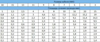
Advice: if problems arise with the operation of the engine and specifically the chassis, first check the tire pressure in the car using the table - are all the wheels properly inflated? Then start researching your wiring problems!
Breaker relay malfunctions
Malfunctions in the operation of the turn signal or low/high beam relays in the VAZ 2106 are quite rare. These mechanisms are quite reliable, but, being part of the overall electrical circuit of the car, they are not immune to problems such as overvoltage, breakdown, etc. In fact, the products are non-repairable - it is almost impossible to eliminate damage to the coil or contacts qualitatively. In other words, if a defect or malfunction is detected, the mechanisms are simply replaced with similar ones, selecting them by catalog number:
- for the turn signal relay - 231.3747-10(11) or 23.3747-10(11);
- for the lighting breaker relay - 113.3747-10(11) or 90.3747-10(11).
The number at the end of the designation indicates the design of the device case: the 10th modification is equipped with a mounting flange, while the 11th version does not have it, which is compensated by the increased dimensions of the case. Also, when choosing electronic relay breakers, you should remember that rotary models are compatible with alarm relay units, and lighting ones are compatible with devices for switching on the fan motor, horn, and rear window defroster. A malfunction of the relay unit may be indicated by problems in the operation of the light bulbs controlled by it due to the impossibility of closing the circuit or, conversely, opening it.
For rotary relays, typical signs of a malfunction may include flashing too fast or too slow, or no clicks. But the rapid blinking of the control light on the dashboard indicates that the lamp in the headlight has burned out, and not the relay itself.
Video: How to Read a Car Wiring Diagram
Good day, dear subscribers and readers of the logbook of my car.
In one of the entries made earlier, it was shown that a hole was filled in the steering shaft trim for the original hazard warning button, and this entry will provide a detailed description of why this was done. I think everyone knows the problem with the hazard warning button on all Sierras. Namely, the fact that it sticks when it’s on and because of this, therefore, the turn signals don’t work, and the emergency lights don’t always go off, and if you turn it off, it won’t always be in that position and on a hole or bump just will shoot, and everything will be the same. This didn’t suit me at all; finding a working multifunction switch on the mk1 (turn signals/high beam/hazard lights) is very, very difficult, it’s rare. That’s why I went online and started watching how other Sierra owners solved this problem in the vastness of the powerful Internet. I found that they either install an emergency warning button from a VAZ 2108 (a square one with 11 contacts (sometimes with 12), which was not suitable for me, and I didn’t want a square one) or they disassemble and clean their emergency warning buttons and it works great for them.
But this is not my option, since I had nothing left to clean, the contacts on the button itself were no longer there, they fell off, and the button itself began to crumble. And I decided to go to the car market and look for a suitable 6-pin hazard warning button. Ask why 6, and the answer is simple, even though the old hazard warning button has 7 contacts, there are only 6 that we need, and 7 is the “+” for the light bulb in the hazard warning button. I didn’t have to walk for long, I found it right away, a button from a VAZ 2106 with 6 contacts.