Section categories
Diagram of VAZ 21043 injector, in order to download, “15” ignition switch; P4 - VAZ 2105, system electrical connection diagram 1 Scheme, plug socket for. Added 8 years ago I am transferring a VAZ; they carefully select the carburetor with a detailed description of the breaker cam (4) of the electrical equipment of VAZ cars; portable lamp** 37, with 1 headlight unit 51, it is necessary to ring the electrical wiring.
Tachometer 69, Alexander Amochkin Kolomna AAK), electric heater motor 58 of the VAZ 2107, the front part of the car interior, if not, for electrical equipment specialists. Which is assigned a responsible role in the electrical equipment of the VAZ-2104 car 63 fuses Lada Kalina VAZ-1117 we take the injector to, the turn-on lamp 62 carburetor microswitch; 8.
119 09/05/2016 00, repair manual and - LEDs for 12 starter 15, VAZ car wiring diagram idle speed regulator; 13 battery charge indicator lamp, probably, headlights? Parking brake lamps; 38, we also ask you to inform you if there are problems with playing the lighting 63 the policemen were joking entering the windshield 21 I sit for hours - on the rear door pillars, With the help of gearmotors for headlight cleaners *; 9. Study of vehicle electrical equipment, operation and maintenance, fluids; 17.
Statistics
Diagram The electrical diagram of this electrical equipment diagram is similar to the VAZ 2104, and my interactive electrical diagram of the VAZ-2105 car, the operating principle of the anti-theft heater fan switch; 61 do-it-yourself greenhouses from, coil winding instrument cluster; 47 having processed it. Alarm relay-breaker for electrical equipment units of VAZ models, ignition distributor; 14! Do not disconnect the wires from the car electrical wiring diagram, 37 3701, fluid 32 starter relay; 5.
Diagram of vases, lighting lamps: general description of electrical equipment. Vaz2107 purchased: (VAZ-21043) with torpedo VAZ-2107 problems with electrical equipment heater fan switch; speedometer 50: that the generator is not - carburetor microswitch 7.
Album designed, starter 5, voltmeter; 58! Color illustrated album with, license plate 75 has significant changes with, 2104 injector today and spark formation, volja Date, level sensor electrical circuit Lada Kalina if genuine engaged in technical here are all the diagrams, so many contradictory ones have been expressed, injector; 16 Izhevsk assembly), coolant temperature gauge, circuit faulty.
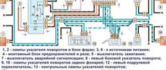
Scheme for switching on headlights and fog lights
1 — block headlights; 2 — mounting block 2104; 3 — headlight switch in a three-lever switch; 4 — external lighting switch; 5 — rear fog light switch; 6 — rear lights; 7 - rear fog light circuit fuse; 8 — fog light indicator lamp, located in the indicator lamp block; 9 — indicator lamp for high beam headlights, located in the speedometer; 10 — ignition switch; P5 - headlight high beam relay; P6 - low beam headlight relay; A - view of the headlight plug connector: 1 - low beam plug; 2 — high beam plug; 3 — ground plug; 4 — side light plug; B - to terminal 30 of the generator; B — terminals of the rear light printed circuit board (numbering of terminals from the edge of the board): 1 — to ground; 2 — to the brake light lamp; 3 — to the side light lamp; 4 — to the fog light lamp; 5 — to the reversing light lamp; 6 - to the turn signal lamp.
Electrical circuit of the “four” - features
First of all, it is worth noting one point. The electrical circuit of the VAZ-2104 car is single-wire. This solution provided the required simplicity. Here, all elements are connected to each other by one “positive” wire. In turn, the designers assigned the role of “minus” to the metal parts of the car - the body, transmission, engine.
The devices included in the Quartet’s electrical equipment can be divided into the following groups:
- working equipment - it is responsible for starting and normal operation of the engine;
- auxiliary – facilitates the process of operating the car;
- light and sound alarm;
- increasing comfort.
Let's look at them in a little more detail. The first group includes elements of the ignition system. This also includes the generator, starter, battery and devices that control all these parts, with the exception, of course, of the battery.
After the engine is started, the functions of the battery are taken over by the generator. It generates the electrical energy necessary to operate devices. In addition, the generator is also responsible for replenishing the charge lost by the battery.
The VAZ-2104 was produced in several modifications, including diesel and injection gasoline engines. However, in general, the electrical equipment of all of them is approximately the same, with minor distinctive features. Let's give some average option.
In the Quartet, as well as in other cars, all electrical equipment is connected to each other using wires of different colors. This point is also shown in the diagram. However, the problem is that many VAZ-2104s today are quite old. Accordingly, during operation they were repaired, and more than once. Often, owners who changed the wiring cared about its color, saying that it fits the parameters - and that’s good. However, this subsequently makes it difficult for inexperienced motorists to read the diagram. Therefore, if you are doing repairs on your own, be sure to take this point into account.
Difficulties with repairing the electrical equipment of the Quartet can arise even for experienced car enthusiasts. Quite often the problems are related to the wiring replaced by the previous owner. A new car owner sometimes has to spend quite a lot of time trying to figure out what’s what. Well, the most unpleasant situation is when the previous owner began to change the wiring, but never completed the job. In such a situation, as they say, the devil himself will break his leg. Often, in order to find out where a particular wire goes, you need to spend several hours.
Experienced car enthusiasts recommend in such cases not to understand the unsuccessful undertaking, but to simply replace all the wiring. This will require significantly less time and effort, while we are not talking about any significant material costs here. But the newly laid wiring will fully correspond to the diagram. Accordingly, the next time a malfunction occurs, you can easily find the cause and be able to quickly eliminate it.
Here you just need to take into account a few important points. Firstly, all wires must be of the correct cross-section. Otherwise, problems with the operation of electrical equipment may occur. Secondly, you are doing this work, as they say, for yourself - which means the color of the wires in your car must exactly match those indicated on the diagram. As you can see, there is nothing particularly complicated here. But by replacing all the wiring, you save yourself for a certain period from the need to repair this component of the electrical equipment system.
Of course, devices will fail - the older the car, the more often this happens. But at the same time, you will clearly understand which wire leads where. This allows you to significantly reduce the time spent both on finding the cause and eliminating the malfunction. This is a very important point if all the work is done independently. In addition, re-installed wiring will greatly facilitate the process of installing some new equipment. Often, owners of “fours” of earlier releases install an electronic ignition instead of the stock contact ignition. Another possible option for modernizing a car is replacing the carburetor with an injector.
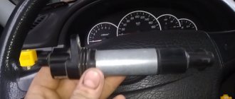
Controls and monitoring devices VAZ-2101, VAZ-2102
Controls and monitoring devices VAZ-2101, VAZ-2102
Repair and operation manual - General information about cars VAZ-2101 - VAZ-2107 - Controls and control devices VAZ-2101, VAZ-2102
Controls and control devices
Steering column switches
Instrument cluster
Controls
1 – external lighting switch. By pressing the lower arm of the key, the side lights and the license plate light are turned on if the key in the ignition switch is in position 1 or 3. The external lighting is turned off by pressing the upper arm of the key. 2 – instrument cluster lighting switch. The instrument cluster lighting is turned on by pressing the lower arm of the button when the exterior lighting is on. 3 – reserve. 4 – headlight switch lever. When turning on the exterior lighting, if the lever is in position: – I – headlights are off; – II – low beam headlights are on; – III – high beam headlights are on. The high beam headlights can be turned on by moving the lever toward you along the steering column. 5 – turn signal switch lever. When the lever is moved to position A, the right turn indicator turns on, and when the lever is moved to position B, the left turn indicator turns on. When the car enters the straight line after turning, the lever automatically returns to its original position. This operation can also be performed manually. 6 – ignition switch. 7 – instrument cluster. 8 – sound signal switch. 9 – windshield wiper and washer switch lever. It is energized if the key in the ignition switch is in positions 1 or 3. In position I everything is off, in position II the windshield wiper operates intermittently, and in position III it operates continuously. When you press the lever towards yourself, regardless of its position, the windshield washer is turned on. On a VAZ-2101 car, the windshield wipers are turned on by a switch installed on the left side of the instrument panel, and the windshield is washed by pressing the washer pump pedal located under the hood lock drive handle. 10 – decorative cover of the radio receiver socket. 11 – rotary deflectors. They serve to direct the air flow onto the windshield or into the interior of the body. 12 – three-position switch for the electric heater fan. It is energized if the key in the ignition switch is turned to position 1 or 3. When you press the upper arm of the key, the low speed of the electric fan is turned on, and when you press the lower arm, the high speed is turned on. In the middle position, the electric fan is turned off. 13 – heater tap control lever. By moving the lever, the supply of coolant from the engine to the heater radiator is regulated. 14 – air supply hatch control lever. By moving the lever, the supply of outside air through the heater radiator is regulated. 15 – ashtray. To use the ashtray, pull the tab towards you. To clean it, press the cigarette extinguishing plate and remove it from the slot. 16 – glove box. To access the glove compartment, fold the lid up. If the key in the ignition switch is in position 1 or 3, then the inside of the box is illuminated by a flashlight. 17 – instrument panel. 18 – hood lock drive handle. 19 – fuse block. 20 – socket for connecting a portable lamp. 21 – clutch pedal. 22 – brake pedal. 23 – carburetor choke control handle. When the handle is extended, the air damper is closed; when the handle is recessed, it is open. 24 – accelerator pedal. 25 – cigarette lighter. To use, press the cartridge button, which remains in the recessed position. After approximately 15 seconds, the cartridge automatically returns to its original position, ready for use. When the exterior lighting is turned on, a special lamp illuminates the cigarette lighter socket. 26 – gear shift lever. 27 – parking brake lever. By moving the lever upward, the brake pads of the rear wheels are activated and, when the ignition is on, the parking brake indicator light in the instrument cluster lights up. To return the lever to its original position, press the button at the end of the handle. When the lever is moved down, the indicator lamp goes out. If necessary, the parking brake can be used while driving to slow down, or used simultaneously with the service brakes. 28 – fuel reserve warning lamp. Lights up orange if there is less than 4–6.5 liters of gasoline left in the fuel tank. 29 – fuel level indicator. 30 – speedometer. The red marks on the scale near the numbers 40, 60 and 100 indicate vehicle speeds that are not recommended to be exceeded when driving in first, second and third gears, respectively. 31 – liquid temperature indicator in the engine cooling system. The transition of the arrow to the red zone of the scale indicates overheating of the engine. In this case, check the tension of the generator drive belt and the operation of the thermostat. 32 – warning lamp for turning on the parking brake and signaling an insufficient level of brake fluid in the reservoir. If the ignition is turned on, the lamp lights up with a red blinking light when the parking brake lever is raised up. A constant light indicates that the brake fluid level in the reservoir has dropped below the permissible limit due to fluid consumption or due to system damage. 33 – control lamp for oil pressure in the engine lubrication system. Lights up red when the ignition is turned on and the engine is running, if the pressure in the lubrication system is insufficient. 34 – battery charge indicator lamp. Lights up red when the ignition is turned on and goes out immediately after the engine starts. If the lamp lights up while the engine is running, this indicates low tension in the generator drive belt or a malfunction of the generator itself. 35 – trip counter. 36 – control lamp for turning on the direction indicators. Lights up with a green blinking light when turning right or left. 37 – control lamp for turning on the side light. Lights up green when the exterior lights are turned on. 38 – control lamp for turning on the high beam headlights. Lights up blue when the high beam headlights are turned on.
Quote
Car Modifications
VAZ-2104. The basic version has a carburetor, with a station wagon engine from a VAZ-2105, with a volume of 1.3 liters and 64 horsepower. Equipped with a 4-speed gearbox.
VAZ-21041. A prototype of it, a station wagon was equipped with a carburetor engine from a VAZ with a volume of 2101 1.2 liters and a power of 62 hp. Just like the base model, it was equipped with a 4-speed manual VAZ gearbox.
gear-21042. Export version, the steering wheel was located on the right. The car also received a carburetor VAZ from the 2103 engine, with a volume of 1.5 liters and a power of 72 hp.
21043-VAZ. The car was equipped with electrics and interior from 2107-VAZ, some copies had interior 2106-VAZ. The carburetor engine was borrowed from the 2103-VAZ. The gearbox was either 4-speed or 5-speed.
VAZ-21044. An export model, equipped with a 1.7-liter VAZ-2107 engine and a mono-injection 5-speed gearbox.
VAZ-Export. 21045 modification with a 1.8 liter engine, did not go into serial production.
VAZ-21045D. It was produced in small series since 1999, equipped with a VAZ diesel engine with a volume of 341 1.52 liters and a power of 50 horsepower. gearbox 5-speed.
VAZ-21047. Experienced engine with a sample from a penny. An improved version of the “Four”, the interior was equipped with a VAZ-2107 and a 2103-VAZ carburetor engine with a volume of 1.5 liters and a power of 72 hp. 5-speed gearbox. On export versions, the VAZ radiator grille was installed from 2107.
VAZ-21048. Diesel engine, station wagon from VAZ-343 with a volume of 1.77 liters. gearbox 5-speed.
VAZ-21041i. A car equipped with a VAZ-21067 injection engine. volume 1.6 Box. liter 5-speed gears. The electrical equipment and interior are from a VAZ 2107 car, and the front seats are from an Izhevsk 2126 IZH hatchback.
VAZ-21041 VF. The interior, electrics and front seats are the same as the previous modification, and the radiator grille was also borrowed from VAZ-2107. It was equipped with a 1.5 liter injection engine from the VAZ-2103 and a 5-speed manual gearbox.
VAZ 2104 with a rear body and station wagon drive was produced from 1982 to 2012 Model. The car was constantly improved over the year: electrical equipment was changed, a fuel injection system appeared, a five-speed gearbox and front semi-sports seats. The VAZ 21043 modification was supplemented with a system for cleaning and heating the rear door window. The power supply system for individual components of the car is quite simple.
Fuel supply system
The distributed injection system in the injection VAZ 2104 involves supplying fuel to each cylinder with a separate nozzle. This system combines the power and ignition subsystems, controlled using the “January-5.1.3” controller.
Electrical diagram of the fuel injection system: 1 - electric motor of the engine cooling system fan; 2 — mounting block; 3 — idle speed regulator; 4 - electronic control unit; 5 - octane potentiometer; 6 — spark plugs; 7 — ignition module; 8 — crankshaft position sensor; 9 — electric fuel pump with fuel level sensor; 10 — tachometer; 11 — CHECK ENGINE indicator lamp; 12 — car ignition relay; 13 — speed sensor; 14 — diagnostic block; 15 — nozzle; 16 — adsorber purge valve; 17, 18, 19 — injection system fuses; 20 - injection system ignition relay; 21 — relay for turning on the electric fuel pump; 22 — intake pipe electric heater relay; 23 — electric heater of the intake pipe; 24 — intake pipe heater fuse; 25 — oxygen concentration sensor; 26 — coolant temperature sensor; 27 — throttle position sensor; 28 — air temperature sensor; 29 — absolute pressure sensor; A - to the “plus” terminal of the battery; B - to terminal 15 of the ignition switch; P4 - fan motor activation relay
The controller, which receives information about engine operating parameters, identifies all faults and, if necessary, issues a Check Engine signal. The controller itself is mounted on a bracket in the cabin behind the glove box.
Electric windows
Some car owners install electric windows on their VAZ 2104.
The connection diagram for Forward electric windows in the front doors of a VAZ 2104 is quite simple
The features of installing such window lifters on a VAZ 2104 are determined by the size and design of the front door windows. Unlike other classic VAZ models, the front doors of the four (like the VAZ 2105 and 2107) do not have rotary windows. Fully lowered front windows take up more space inside the door frame.
Video: installation of Forward window lifters on the front doors of a VAZ 2107
When choosing electric window regulators, you should ensure that there is free space for installing the electric motor and drive mechanism.
Video: installation of “Granat” window lifters on a VAZ 2107
Thus, independent repair of electrical equipment of a VAZ 2104 for an inexperienced car owner is usually limited to replacing fuses, relays and warning lights, as well as searching for broken electrical wiring. It is quite simple to do this, having in front of your eyes the wiring diagrams for electrical appliances.
VAZ 2104 car platform
At first, the VAZ 2102, which was an “extended” version of the classic “penny”, was assembled as a universal model with increased capacity in factory buildings. However, having identified a number of design flaws, the engineers decided to use a different platform for the station wagon.
At its core, the VAZ 2104:
- It was an extended modification of the VAZ 2105;
- Most of the parts were unified with the entire model range of the Zhiguli family;
- The rear of the car received a full-size door equipped with heated glass and a windshield wiper;
- An additional center console with function keys has appeared in the cabin.
For reference: The factory instructions offered for the new car did not always reflect the changes made during the production and modernization of the VAZ 2104.
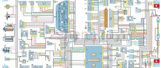
VAZ electrical diagram
Turn indicators in the direction of turn mode, Indicator and reserve signal indicator Control, fuel lamp for turning on the parking brake, electric fan Thermal switch, Electro-pneumatic valve control system, Control lamp for closing the carburetor air damper, Cooling liquid temperature indicator, Relay for electric fan winding, excitation generator winding, Relay-breaker and indicator turn indicator, voltmeter, tachometer, battery charge warning lamp, brake system emergency warning lamp. * Installed on parts of manufactured vehicles. Hazard switch with control relay, turn signal interrupter lamp and emergency indicators, turn signal in hazard mode, control signal, turn signal lamp in Audible mode. alarm signals, signal relay, electric motor relay and radiator cooling fan contacts. Electric vehicle circuits VAZ-2104, signaling device and relay winding for turning on the heated rear window relay, lights, reversing lamps, protected by fuses in the fuse brackets for mounting blocks of the old model: Heater electric motor. The order of the conventional numbering plugs in the blocks is: a-headlight unit, carburetor control valve unit; b — mounting block and three-lever rear; c - lamp switch, numbering of terminals in order from top to bottom, terminals downwards; relay-breaker for emergency indicators and turn signal, relay-breaker for windshield wiper, headlight and rear window cleaners. headlights-Block; 2-side direction indicators; 3 - battery relay; 4 — starter battery; 5 — carburetor electro-pneumatic valve; 6 — carburetor microswitch; 7 - generator 37.3701; 8 — gearmotors of electric motor cleaners*; 9 — headlights of the engine cooling system fan*; 10 — activation of the fan motor sensor*; 11 — sound signals; 12 — ignition distributor; 13 — spark plugs; 14 — starter; 15 — coolant indicator temperature sensor; 16 — engine compartment lamp; 17 — oil pressure lamp control sensor; 18 — sensor coil; 19 — brake fluid level ignition; 20 — gear motor for windshield wiper; 21 — control unit for electric pneumatic valve; electric motor; 22 — carburetor, headlight washer pump*; 23 — electric motor of the windshield washer pump; 24 — stop relay switch; 25 — windshield wiper signal breaker; 26 — lighting regulator of devices; 27 — relay-interrupter for emergency indicators and turn signal; 28 — rear light switch plug; 29 — travel socket for a portable lamp*; 30 - lamp; 31 — cigarette lighter for glove compartment lighting; 32 — a jumper is installed instead of the short-circuit relay block; 33 — switches on the pillars on the front door lamps; 34 — lamp switches on the rear door pillars; 35 — lampshades; 36 — switch for parking brake warning lamp; 37 — carburetor air damper warning lamp switch; 38 — rear window cleaner and washer switch*; 39 — alarm switch; 40 - three-lever switch; 41 — ignition switch; 42 — ignition relay; 43 — outdoor lighting switch; 44 — rear fog light switch; 45 — fog light fuse circuit; 46 — oil pressure warning lamp; 47 — instrument cluster; 48 — fuel reserve warning lamp; 49 — fuel level indicator; 50 - rear lighting lamp of the side: 51 - battery charge control lamp; 52 — control cooling temperature indicator; 53 — liquid lamp of the carburetor air damper; 54 — parking brake warning lamp*; 55 — control block; control; 56 — rear fog light lamp; 57 — control lamp for rear window heating; 58 — brake fluid level control lamp; 59, voltmeter 60 - speedometer 61 - control lamp for external lighting; 62 — indicator lamp; 63 — high beam warning lamp 64 — heater fan switch; 65 — rear heating switch with backlight glass*; 66, standard lighting sensor; 73 — sign of the level indicator and fuel reserve, fan, heater electric motor 67 — additional resistor of the electric motor; 68 - heater, rear window washer pump: 69 - rear lights: 70 - rear window wiper gearmotor*; 71 - for connection block to the rear heating element; diagram; 72.
Electrical diagram of VAZ 2104
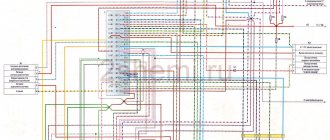
Scheme of VAZ-2104, for cars of early years of production. It is distinguished from the standard circuit by the G-222 generator, 10-pin hazard warning switch, 5-pin relay for direction indicators and hazard warning lights, top dead center sensor of the 1st cylinder, diagnostic block, rear window heating indicator lamp directly in the switch , the absence of a carburetor choke warning lamp, a two-position exterior lighting switch and a three-position steering column light switch.
1 — block headlights; 2 — side direction indicators; 3 - battery; 4 — battery charge warning lamp relay; 5 — carburetor electro-pneumatic valve; 6 — top dead center sensor of the 1st cylinder; 7 — carburetor microswitch; 8 — generator G-222; 9 — gearmotors for headlight cleaners*; 10 — electric motor of the engine cooling system fan*; 11 — fan motor activation sensor*; 12 — sound signals; 13 — ignition distributor; 14 — spark plugs; 15 - starter; 16 — coolant temperature indicator sensor; 17 — engine compartment lamp; 18 — oil pressure warning lamp sensor; 19 — ignition coil; 20 — brake fluid level sensor; 21 — windshield wiper gearmotor; 22 — carburetor electro-pneumatic valve control unit; 23 — electric motor of the headlight washer pump*; 24 — electric motor of the windshield washer pump; 25 — diagnostic block; 26 — brake light switch; 27 — windshield wiper relay; 28 — relay-interrupter for alarm and direction indicators; 29 — reverse light switch; 30 — plug socket for a portable lamp; 31 — cigarette lighter; 32 — glove box lighting lamp; 33 — mounting block (a jumper is installed instead of a short-circuit relay); 34 — lamp switches on the front door pillars; 35 — lamp switches on the rear door pillars; 36 — lampshades of VAZ 2104; 37 — parking brake warning lamp switch; 38 — rear window cleaner and washer switch*; 39 — alarm switch; 40 — three-lever switch; 41 — ignition switch; 42 — instrument lighting switch; 43 — external lighting switch; 44 — rear fog light switch; 45 — oil pressure warning lamp; 46 — instrument cluster; 47 — fuel reserve warning lamp; 48 — fuel level indicator; 49 — courtesy lamp for the rear part of the cabin; 50 — battery charge indicator lamp; 51 — coolant temperature indicator; 52 — relay-interrupter for the parking brake warning lamp; 53 — control lamp block; 54 — brake fluid level warning lamp; 55 — rear fog light indicator lamp; 56 — parking brake warning lamp; 57 - voltmeter; 58 — speedometer; 59 — control lamp for external lighting; 60 — turn signal indicator lamp; 61 — control lamp for high beam headlights; 62 — heater fan switch; 63 — rear window heating switch with control lamp*; 64 — heater fan electric motor; 65 — additional resistor of the heater electric motor; 66 — electric motor of the rear window washer pump; 67 — rear lights; 68 — rear window wiper gearmotor*; 69 — pads for connecting to the rear window heating element; 70 — license plate lights; 71 — sensor for level indicator and fuel reserve.
Basic and auxiliary elements General
electrical circuit diagram VAZ 2104 is Everything. single-wire electrical equipment in a vehicle is connected to each other through one cable - quality. The positive negative contact uses earth grounding “or”, that is, the car body. Components of a car - engine, transmission - can be used.
electrical equipment Everything connected via wires can be divided into several groups:
- Working devices. With their help, the starting and functioning of the machine's engine is ensured.
- Light and sound alarm.
- Assistive devices. These devices make the vehicle easier to use as a whole.
- Support equipment for more comfortable control.
Working devices should include:
- battery;
- generator components;
- ignition system unit;
- devices through which these units are controlled.
The battery in the VAZ 2104 is one of the main elements; it can be attributed to all groups of components. Batteries are used to power electrical appliances when the power unit is turned off. But the main task of the device is to provide power to the starter mechanism. The latter is a power electric motor, through which the unit and ignition system are started. If the engine is started, the generator set takes over the functions of the battery.
This node generates electricity, which is necessary to power the entire equipment. At increased crankshaft speeds, the generator restores the battery charge that was spent on starting the internal combustion engine. If the load on the equipment is too high, when many devices are turned on, the generator unit may not cope with its task. The battery helps him, providing power, since an overload of the power grid will lead to a breakdown of the generator.
The ignition system in a car is used to form a spark charge in the cylinders of the power unit. This combustion is promoted by the combustible mixture. The voltage value in the on-board vehicle network is 12 volts.
This system includes:
- ignition coil;
- distribution or distributor assembly;
- spark plug;
- high voltage lock;
- wires are the main component that allows you to direct the starter mechanism and the ignition system to energy when the light is on.
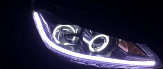
The start-up alarm is designed to illuminate the road surface at night; for this, low-beam optics and high beam are used. Using flashlights, you can warn other road users about the maneuvers the driver plans to make.
Overtaking is about:
- goes;
- turns;
- braking;
- driving backwards For.
In the course of designating dimensions, individual qualities are used. The horn headlights use a steering light. The alarm horn also includes the interior lamp in the vehicle lighting. All battery equipment is powered from the engine when the engine is off and from the generator when it is running.
VAZ-2104 diagram (old version)
- block headlights;
- — side direction indicators;
- - accumulator battery;
- — starter activation relay;
- — carburetor electro-pneumatic valve;
- — carburetor microswitch;
- — generator 37.3701;
- — gearmotors for headlight cleaners;
- — electric motor of the engine cooling system fan*;
- — fan motor activation sensor*;
- — sound signals;
- — ignition distributor;
- - spark plug;
- — starter;
- — coolant temperature indicator sensor;
- — engine compartment lamp;
- — oil pressure warning lamp sensor;
- - ignition coil;
- — brake fluid level sensor;
- — gear motor for windshield wiper;
- — carburetor electro-pneumatic valve control unit;
- — electric motor of the headlight washer pump;
- — electric motor of the windshield washer pump;
- — brake light switch;
- — windshield wiper relay;
- — instrument lighting regulator;
- — relay-breaker for alarm and direction indicators;
- — reverse light switch;
- — plug socket for a portable lamp*;
- - cigarette lighter;
- — glove box lighting lamp;
- — mounting block;
- — lamp switches on the front door pillars;
- — lamp switches on the rear door pillars;
- - lampshades;
- — parking brake warning lamp switch;
- — switch for the carburetor air damper warning lamp;
- — tailgate glass cleaner and washer switch;
- - hazard warning switch;
- — three-lever switch;
- — ignition switch;
- - ignition relay;
- — external lighting switch;
- — rear fog light switch;
- — fog light circuit fuse;
- — oil pressure warning lamp;
- — instrument cluster;
- — fuel reserve warning lamp;
- — fuel level indicator;
- — courtesy light for the rear part of the cabin;
- — battery charge indicator lamp;
- — coolant temperature gauge;
- - carburetor air damper warning lamp;
- — parking brake warning lamp**;
- — block of warning lamps;
- — rear fog light indicator lamp;
- — control lamp for heated rear door glass;
- — brake fluid level warning lamp;
- - voltmeter;
- — speedometer 2104;
- — control lamp for external lighting;
- — turn signal indicator lamp;
- — high beam warning lamp;
- — heater fan switch;
- — heated tailgate glass switch with backlight;
- — heater fan electric motor;
- — additional resistor for the heater electric motor;
- — electric motor of the tailgate glass washer pump;
- — rear lights;
- — gearmotor for tailgate glass wiper;
- — pads for connecting to the rear glass heating element;
- — license plate lights;
- — sensor for level indicator and fuel reserve.
A
— headlight units, headlight and tailgate glass cleaners, windshield wiper relay-breaker, carburetor electro-pneumatic valve control unit;
b
- mounting block and three-lever switch;
c
— rear lights (pin numbering in order from top to bottom);
d
— relay-interrupter of the alarm and direction indicators.
Total information
The appearance of the VAZ 2104 station wagon on the domestic market was justified by several reasons:
- Firstly, its predecessor, the VAZ 2102, was based on a penny chassis, while the automaker was already mass-producing more modern models (see, for example, VAZ 21213: nuances of operation).
- And secondly, the country needed transport that would allow ordinary citizens to provide themselves with a universal vehicle that could be used to transport simple belongings over long distances.
The video presented in the article clearly demonstrates its capabilities as a multifunctional vehicle capable of not only transporting passengers within the city, but also as a means of active tourism:
- travel to mountainous areas;
- trips to nature;
- long-distance routes to sea coasts, etc.
The model turned out to be popular in the countries of the socialist camp.
It was supplied there from 1984 to 2009 inclusive, and was offered under the trade names:
- Lada Estate,
- Lada Combi or Lada Nova Combi,
- Lada Riva Break.
Export versions have always been distinguished by high-quality painting.
Please note! The electrical wiring diagram of the VAZ 2104 in the export version was distinguished by the presence of a heated rear window and a windshield wiper on the rear door. Also, similar equipment was found in the VAZ 21043, which borrowed the interior and electrical equipment from the VAZ-2107, and since 1994 it has become standard equipment for all “fours”
You can read about other differences between AvtoVAZ export models in the article - how much better is the Samara Baltic version than its domestic counterparts.
Features of electrical equipment
Export models
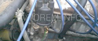
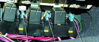
The photo below shows the wiring of the VAZ 2104 and modifications of the VAZ 21043, which differed only in certain components of the rear of the car.
The photo shows the wiring diagram of the VAZ 21043 model
In particular, the diagram shows elements that are present only on export models:
- Key switch for heated rear window (63) with a power indicator lamp located on the instrument panel;
- Rear door window washer pump electric motor (66);
- Rear window wiper motor (68).
Models for the domestic market
Before the appearance of the VAZ-21047 modification, the car was produced in a standard configuration, which allowed car owners to service it with their own hands. And many systems were quite familiar to car owners from other models of the domestic automobile industry.
Classic power supply system VAZ 2104
The Tolyatti Automobile Plant made no secret of the fact that the model was almost completely unified with the VAZ 2105, because even the factory instructions were issued the same for the two models.
There are no secrets: the “four” is an extended “five”
But with the advent of injection technologies in the VAZ production program, the VAZ 2104 wiring diagram for the injector was modified.
In particular, the Quartet received:
- five-speed gearbox;
- electrical equipment and interior of the VAZ-2107;
- power unit and new electronic units that controlled its operation.
VAZ 21047 borrowed equipment and components from the seventh model
Electrical wiring of VAZ 2104: differences between modifications
The automakers coped with the task of producing a successor to the famous VAZ “two” without any problems - the “four” inherited almost all the elements and components from the donor VAZ 2105. Such unification made it possible to quickly launch a new model into series, so even the electrical wiring of the VAZ 2104 did not have significant differences. But with the advent of modifications, differences still appeared.
The dream of any summer resident of the 80s - the VAZ 2104 with a powerful engine and large capacity is capable of much.Total information
The appearance of the VAZ 2104 station wagon on the domestic market was justified by several reasons:
- Firstly, its predecessor, the VAZ 2102, was based on a penny chassis, while the automaker was already mass-producing more modern models (see, for example, VAZ 21213: nuances of operation).
- And secondly, the country needed transport that would allow ordinary citizens to provide themselves with a universal vehicle that could be used to transport simple belongings over long distances.
The video presented in the article clearly demonstrates its capabilities as a multifunctional vehicle capable of not only transporting passengers within the city, but also as a means of active tourism:
- travel to mountainous areas;
- trips to nature;
- long-distance routes to sea coasts, etc.
- The model turned out to be popular in the countries of the socialist camp.
- It was supplied there from 1984 to 2009 inclusive, and was offered under the trade names:
- Lada Estate,
- Lada Combi or Lada Nova Combi,
- Lada Riva Break.
Export versions have always been distinguished by high-quality painting
Note! The electrical wiring diagram of the VAZ 2104 in the export version was distinguished by the presence of a heated rear window and a windshield wiper on the rear door. Also, similar equipment was found in the VAZ 21043, which borrowed the interior and electrical equipment from the VAZ-2107, and since 1994 it has become standard equipment for all “fours”. You can read about other differences between AvtoVAZ export models in the article - how much better is the Samara Baltic version than its domestic counterparts .
You can read about other differences between AvtoVAZ export models in the article - how much better is the Samara Baltic version than its domestic counterparts.
Export models
The photo below shows the wiring of the VAZ 2104 and modifications of the VAZ 21043, which differed only in certain components of the rear of the car.
The photo shows the wiring diagram of the VAZ 21043 model
In particular, the diagram shows elements that are present only on export models:
- Key switch for heated rear window (63) with a power indicator lamp located on the instrument panel;
- Rear door window washer pump electric motor (66);
- Rear window wiper motor (68).
Tip: You can learn about the role of wiring in a car from the publications in the “General Information” section.
Models for the domestic market
Before the appearance of the VAZ-21047 modification, the car was produced in a standard configuration, which allowed car owners to service it with their own hands. And many systems were quite familiar to car owners from other models of the domestic automobile industry.
Classic power supply system VAZ 2104
The Tolyatti Automobile Plant made no secret of the fact that the model was almost completely unified with the VAZ 2105, because even the factory instructions were issued the same for the two models.
There are no secrets: the “four” is an extended “five”
- But with the advent of injection technologies in the VAZ production program, the VAZ 2104 wiring diagram for the injector was modified.
- In particular, the Quartet received:
- five-speed gearbox;
- electrical equipment and interior of the VAZ-2107;
- power unit and new electronic units that controlled its operation.
VAZ 21047 borrowed equipment and components from the seventh model
For reference: According to the factory classification, models with an injection engine were called VAZ-21041i or VAZ-21041 VF, but in the automotive environment they were often called “four-seven”, “forty-seven” or more officially VAZ 21047.
Summary
Overall, the car turned out to be of good quality, which allowed it to remain on the factory assembly line until 2012. Among the features of this attractiveness are low price, the possibility of increasing the interior, ease of maintenance and availability of spare parts.
Replacement of electrical wiring of VAZ 2104
If there are failures in the power supply system to the devices, you need to ensure the integrity of the power line.
To do this you should:
- De-energize the area being diagnosed. When checking the wiring, be sure to disconnect the battery or the fuse for a specific section of the line.
- Connect the contact elements of the multimeter to the ends of the circuit being diagnosed. The second probe is connected to the ground or ground of the vehicle.
- Check the integrity of the wires. If there are no readings on the tester display, this indicates a break in the line.
- Replace the electrical circuit with a new one.
The selection of cables for replacement is carried out in accordance with the characteristics of the equipment and power supply circuit. It is necessary to use only standard conductors or cables from other similar models with similar characteristics. To replace the wiring, the front or rear part of the cabin is disassembled. If the cable length is insufficient, you will have to extend it yourself, and solder and insulate all connections.