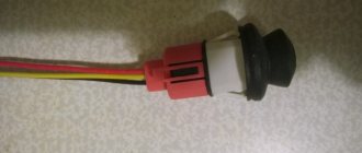
Purpose of the fuse mounting block
The figure shows the location of the blocks under the signs A and B.
The mounting areas have one purpose - to place the safety elements in one place. This allows you to quickly and easily find the damaged element without disassembling half the machine.
The external module (under the hood) looks like a black plastic box. Elements responsible for the power supply circuits of the power plant and main equipment are mounted here.
The indoor (cabin) unit is responsible for auxiliary networks and devices. On cars after 2011, the arrangement of individual elements has changed, but the principle remains the same.
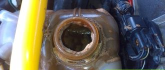
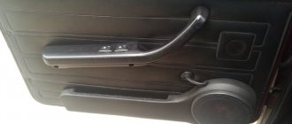
Fuse box in the passenger compartment
It is thoughtfully located under the glove compartment.
The photo shows the module without a protective cover and lining. Here, each element is responsible for a specific device or circuit. The photo above shows the first generation shield. In the first versions of the machine from 2006-2007, some instruments and elements are missing, which simplifies the design of the module. After 2008, the device was updated, new parts and elements appeared. Therefore, the modified pinout needs to be further described.
Under the hood
It is closed with a special lid that prevents dust and dirt from entering the compartment. Here the inserts are primarily responsible for the powertrain systems and carrier electronics. To allow installation of additional equipment, the installer has spare sockets.
Fuses Focus 2 dorestayl
The first modifications of the car had a simplified layout of inserts and relays, relative to the last years of production. The modules do not contain batteries for complex devices and equipment.
Fuses for the restyled Focus 2
After the update, the element panel has changed slightly in appearance. The type of device remains the same, the main difference is in the type of power supply and connection.
212-2 Repair Focus I
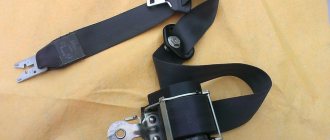
Fuse and relay mounting blocks
To replace a fuse or relay, disconnect the negative cable terminal from the battery.
There are tongs on the cover of the additional block.
. with which we remove the fuses. Also on the cover, symbols show the location of the fuses, the electrical circuits they protect and the purpose of the relay. To access the interior fuse box.
. remove the cover. On its inside there are symbols indicating the circuits protected by fuses. It is more convenient to remove the fuse with pliers. To replace relays located in the mounting block above the fuses.
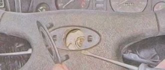
. Using a Phillips screwdriver, unscrew the five screws securing the shelf installed under the instrument panel on the driver’s side.
We move the shelf away from the instrument panel. The diagnostic connector block is fixed on the shelf.
Using a screwdriver, pry up the latch.
. remove the diagnostic connector block from the shelf.
Using a “7” head, unscrew the two bolts securing the mounting block to the bracket.
Press the two latches.
. remove the block from the bracket.
We replace the faulty relay.
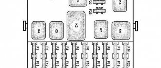
Main mounting block located in the cabin
: 1 - fuse block (number, color, rated current of fuses, as well as protected circuits are indicated in the table); 2 - reserve; 3 - starter relay; 4 — relay for intermittent operation of the tailgate glass wiper; 5 — relay for intermittent operation of the windshield wiper; 6 — sound signal relay; 7 - time delay block relay; 8 - relay for heating the rear window/tailgate glass and exterior rear-view mirrors.
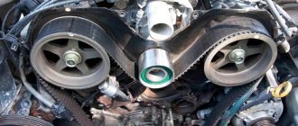
Additional mounting block located in the engine compartment
: 1 — fuse block (number, color, rated current of fuses, as well as protected circuits are indicated in the table); 2 - ignition relay; 3 - reserve; 4 — windshield heating relay; 5 — headlight high beam relay; 6 — low beam headlight relay; 7 — main relay of the engine control system; 8 — fuel pump relay; 9 — air conditioning compressor relay; 10 - reserve; 11 — relay for additional fan of the engine cooling system; 12 — engine cooling fan relay.
Fuse F65, which protects the central locking circuit, is installed on the back of the main mounting block. To remove some components, such as the brake master cylinder, it is necessary to remove the mounting block installed in the engine compartment. But the block does not have connecting connectors - the wires of the harness are connected to the terminals of each fuse and relay directly. This makes it more difficult to disconnect the wires from the unit. Therefore, in this situation, disconnect the battery.
Fuse diagram
The figures above show the engine compartment and interior fuse areas of versions 2002-2005. The location of the parts is relevant for gasoline and diesel engines. The factory decoding will help you understand what the marks on the diagram mean.
In the version after restyling, the location and marking of the inserts differ noticeably, which can cause certain difficulties.
Fuse box pinout
The procedure is complex and is only suitable for use in specialized workshops. The module cannot be repaired if part of the board is burned out - the unit is completely replaced.
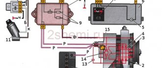
Main unit
The external power supply is located in the engine compartment of the Chevrolet Lanos. The block itself is protected on top by a lid, which can be removed by pressing a couple of latches on the sides. On the back of the cover you will find the electrical diagram of the unit and several spare fuses. Main block diagram:
In reality, the external block looks like this:
It contains 20 PP marked EF and 11 relays, which are marked with the letter K. Before changing any element of the block, you need to know in which device circuit it is connected. PP are responsible for the following elements:
Where are they located?
Regardless of the generation before restyling or restyling, year of manufacture and modification, the location of the fuse boxes is no different. Also, the position is the same in station wagon, sedan and hatchback bodies.
The head module is located near the battery and covered with a special cover. The auxiliary part on the 2004 car with right-hand drive is located on the other side of the car, which makes access to the panel easier.
The rear luggage compartment socket is also installed in one place; after reworking the car, its location has not changed.
An important point is the location of the fuse links themselves. The updated system has more fuses and relays, and in the Max version there are even more elements. Looking at the installer's diagram, you can also see that the parts are in completely different places.
Starter fuses and relays
On a pre-Restyle car, the elements responsible for the launcher are located under the numbers F13 and R13 in the engine compartment. The updated version of the machines is equipped with a remote fuse mounted on a special bracket.
Radio tape recorder
Element 58 of the internal block is responsible for powering music in the first generation. The radio is powered by insert 68. The bifurcated line allows for stable operation of the tape recorder and other units as power increases.
The second generation of the car involves powering the audio system from part No. 112.
Cooling Fan
It is turned on using several elements at once. Fuse F1 and 15 of the external unit are located in the most visible place and have the same purpose, regardless of car modifications. The relay for turning on the radiator blower installation is located in different places. For a car without air conditioning, the relevant number is R12, and where there is a heating system without air conditioning, if it breaks down, you need to pay attention to R14.
Trunk
The power supply system for the socket at the end of the cabin is complex.
In the first generation, fuse 59 is responsible for the operation of the contact group; energy is supplied to the auxiliary element through insert 39, which also serves as cigarette lighter protection. After the update, the manufacturer immediately thought about the power supply to the trailer terminal and installed one element on the socket and lamps of the trailer hitch. This is part #119.
The standard trunk lid lock contacts pass through the central locking system. The head module acts as a fuse and controller. There are no relays here; in the hatchback and sedan versions, their role is played by buttons.
After opening the cargo compartment, the lighting is activated. Inserts No. 80 and 104 for versions before and after restyling are responsible for the lamp circuit.
Wiper fuse and relay
The first version of the car had protective elements for the power supply circuit and washer control removed from the blocks - the parts were located near the motor.
After updating the components, the manufacturer placed the front fuse at number 129, and the rear fuse at position 131. There is one fuse for both sides and is located under the hood (R6).
Reverse
Initially, fuse 84 was responsible for the operation of the lamp and the inclusion of the reverse gear light. After the update, element 141 began to perform its function.
The relay is only on the machine - these are R1 and 3 of the main mounting block.
Generator fuse
On the second generation Focus, the protective insert is located in the engine compartment, on the wing. The element is embedded in the power cores of the device. It can be found in the break in the positive wire.
Heater fuse
R10 and F10 are responsible for powering the heater motor. It is unacceptable to connect additional equipment to the elements - this may cause overload of the circuit.
Dimension fuse
Voltage is supplied through inserts No. 45, 48 and 71 of the cabin unit. In the new version of the car, the location of the part corresponds to insert No. 110/113/135. Fuses 124 and 125 are responsible for adjusting the dimensions on the left and right sides.
Relyushka is also located here under number K5.
central locking
It is controlled by fuse F55 and 77. It supplies power to the relay installed in the central locking unit in the car door. For the restyling version, it is moved to the R3 position.
Power window fuse
The system is powered by inserts No. 63 and 127 for lowering and raising the glass. The old generation of the machine is equipped with inserts in the lift modules.
Wiper
The headlight washer system is fed through main unit fuse F23.
In winter, users often encounter burnout of 47/136 inserts (before and after restyling). The elements supply voltage to the heating of the pressure system jets and the pump motor.
The wipers are powered through the 50/129 elements, and the rear window is powered through the 78/131 numbers of the standard circuit.
The windshield washer drive system is controlled by relay R9.
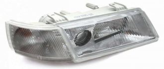
Light fuse
The operation of the high and low beam lamps is adjusted separately for each side. In FF2 this is:
- 37/38 for left and right optical element high beam mode;
- 60/61 low for each side.
In the version after restyling, the indicated elements correspond to the numbers:
- 139/140;
- 142/143.
The headlight switches are located near the light module.
Fog lights
Standard elements on the car are controlled by one fuse 69 and 116 for the first and second generation of cars. At the same time, the power supply to the left and right parts of the onboard fog lights is looped into one circuit.
Such a PTF power system is a disadvantage - if the insert burns out, the entire circuit fails completely.
Headlight adjustments
The standard corrector operates through fuse 66 in the first generation. The version after restyling is equipped with an insert in the module itself.
Number plate illumination
The system operates through inserts No. 117/73 for new and old mounting blocks.
Immobilizer
The security module of the machine is a separate unit with a self-sufficient system of protection against voltage surges and overloads. There is no need to look for the corresponding fuse in the mounting block.
Ignition fuse and relay
The system is complex and confusing. There are 2 fuses 12 and 25 of the engine compartment. There is also a main relay R6 and an auxiliary relay R8.
Signal fuse
Stop lamps in different versions of the car are powered through 74 and 132 for the old and new generations, respectively.
The sound signal protection is installed in the device housing. The relay is mounted in the engine compartment under the number R2.
Accumulator charging
The generator system has its own fuse and relay, located separately. The parts can be found on the right fender of the car.
Climate control
Relay R11 supplies power to the climate system inside the car. The safety insert is marked in the block as R29.
Dashboard
The standard insert F46 of the cabin module is responsible for powering the dashboard in the old generation.
The new version is powered from the battery through fuse 107. Additional tidy options are covered by part 108. After turning the lock, voltage is supplied through element 114.
Lambda probe
The photo shows the location of the oxygen sensor fuse.
Parktronic
The separate parking assistant module is equipped with separate fuses and relays. You should look for elements near the block.
Airbags
The units are protected by 65/122 safety inserts for the first and second generation of the car.
Heated seats
The new generation of cars has this option. The heating elements are protected by insert No. 121 or 86. The element is located in the interior block of the system.
ABS fuse
There are three inserts in the traction control system. Elements F7/8 protect sensors and hydraulic drives from power surges. Element F19 is responsible for the operation of the ABS control unit.
The new generation does not have such a system; it is imitated by a more advanced device.
Speedometer
The fuse is missing and not located in the mounting block. The electronic module is responsible for protection against overvoltage; it also reads data from the sensor and transmits it to the device.
Turn signals
For them, inserts are not mounted in the main block. The elements are located under the dashboard to make them easier to access during maintenance. The devices are located near the driver's feet.
Mirror fuses
The rear view elements are also protected by separate inserts. 42 and 123 are responsible for heating the reflective surface for the old and new versions of the car.
The latest generation also has the ability to fold the mirrors; the servo drive is protected through element 79.
Door fuse
The electrical equipment of the doors of the dorestyle version is looped on one element No. 55. After updating there were two parts, one for each No. 133/134 for the left and right sides.
Heated windshield
There is no heating device as such in most versions of the machine. Heating occurs in a classic way - using a cabin heater.
ESP fuse
Insert No. 19 of the engine compartment is responsible for the new generation traction control system.
Alarm fuse
Modern systems do not have remote protection elements against power surges. You should not look for insertions in common blocks.
Automatic transmission fuse
The electronics of the standard machine are brought out through the main block insert numbered 30 and 75.
Power steering
The power steering unit is also located here. Element 22 is mounted under the hood.
Cruise control fuse
Depending on the configuration and year of manufacture of the car, the power to the system passes through inserts 53/29 of the engine compartment block or 20 and 30.
Relay Focus 2: restyling and dorestyling
Due to the similarity of the internal design of the car before and after the update, the main elements are in the same places and are responsible for strictly defined devices.
Engine relay
Element R6 is located in the main block. Through it, the power plant and the process of its operation are controlled.
Generator voltage regulator relay
It is removed from the mounting block and is located on the fender of the car. This design is relevant for everyone, including VALEO.
Solenoid relay
On the Focus it is located in a classic way - on the starter itself. A Bosch unit is used here. A fairly reliable installation that meets the modern requirements of motorists.
Location of fuses on Ford Focus 2
If one of the electrical devices on your Ford Focus 2 stops working, do not rush to sound the alarm and urgently make an appointment with an auto electrician for service. The electrical circuit of any car contains fuses that blow during power surges, thereby protecting the circuit from overloads and fire. If one of the electrical appliances in the car stops working, first check whether the fuses responsible for it are working properly. Most often, they are the root cause of failure of electronics in a car.
As in most cars, the Ford Focus 2 electrical circuit contains 2 fuse blocks. Below we have described which block is responsible for what and where it is located.
Fuse layout in the main fuse box:
- 36 - RSM
- 35 - valve fuse, RSM
- 34 - fuse for ignition coil, injectors
- 33 - fuse for the bypass valve of the intermediate cooling of the diesel engine
- 32 - oxygen sensor fuse
- 31 - battery charging fuse
- 30 - gearbox fuse, RSM
- 29 - climate control system fuse
- 28 - spark plug control
- 27 - air conditioning compressor
- 26 - gearbox
- 25 - ignition fuse
- 24 - auxiliary heater fuse
- 23 - washer fuse
- 22 - power steering fuse
- 21 - auxiliary heater fuse
- 20 - sound alarm
- 19 - ABS fuse
- 18 - inverting power amplifier
- 17 - roof
- 16 - fuse for the left windshield heater
- 15 - engine cooling fan fuse
- 14 - fuse for the right windshield heater
- 13 - starter fuse
- 12 - ignition relay
- 11 - starter and instrument fuse
- 10 — climate control fan
- 9 - power unit fuse
- 8 - fuse for dynamic stabilization valves, anti-lock braking system
- 7 - pump of dynamic stabilization system, anti-lock braking system
- 6 - glow plug fuse
- 5 - auxiliary heater fuse
- 4 - fuse box
- 3 - fuse box
- 2 - power steering fuse
- 1 - cooling fan fuse
Didn't find the fuse that corresponds to the device you need? There is another fuse box located inside the car. It can be found under the glove compartment.
Fuse layout in the Ford Focus interior:
- 143 - left low beam fuse
- 142 - right low beam fuse
- 141 — electric rear view mirror, reverse dimensions
- 140 - left high beam fuse
- 139 - right high beam fuse
- 138 - transmission, accelerator, power unit
- 136 - fuses for jets and washer pump
- 135 — night illumination
- 134 - driver's door electrics, central locking
- 133 — passenger door electrics, central locking system
- 132 - brake light
- 131 - rear wiper fuse
- 130 - not used
- 129 - windshield wiper fuse
- 128 - not used
- 127 - window fuse
- 126 - keyless control system
- 125 - fuse for right dimensions
- 124 - fuse for left dimensions
- 123 - fuse for heated mirrors
- 122 - airbag
- 121 — heated front seats
- 120 - rear right door electrics
- 119 — power socket in the trunk
- 118 - rear left door electrics
- 117 — number plate illumination
- 116 - fuse for headlights and fog lights
- 115 - external lighting from the generator
- 114 - immobilizer, powered by generator
- 113 — sidelights
- 112 - audio system fuse
- 111 - fuel pump
- 110 - switching lighting from the generator (during the daytime)
- 109 — additional power socket at the rear, cigarette lighter
- 108 — navigation system, audio system
- 107 - on-board diagnostic system, power supply of devices from the battery
- 106 - keyless control system
- 105 - rear window heater fuse
- 104 - interior lighting
- 103 - external lighting from battery
- 102 - remote control receiver, diesel combustion product filter, steering column, heater regulator
- 101 - roof drive, driver's seat drive, sunroof drive
- 100 - power supply of electronic modules from the ignition switch
Replacing parts
The cause of the block board failure is a sudden voltage drop. The process melts the contacts and can kill the device. Water ingress is also a common cause. Any electronics are afraid of moisture and dust.
Replacing the generator regulator relay
After you have learned how to check the voltage regulator and determine that the module is faulty, you should replace it. The procedure itself looks extremely simple. The wiring chip is disconnected from the terminal. Next, the block is unscrewed and replaced with a new element.
Replacing the windshield wiper relay
You will need to pull the device body. Insert the working part into the vacant space.
Replacing the wiper relay
The procedure is similar to changing other elements.
Replacing the solenoid relay
It is more difficult to replace the retractor element, but it is possible to do it yourself.
- Place the car on a level surface and raise the handbrake all the way.
- Remove the terminals from the battery.
- Get under the car and unscrew the 9 engine protection screws.
- Next, the starter itself is shown. Here you will need to disable the chips of the interfering elements of the on-board circuits.
- Next, you need to unscrew the three screws that secure the starter to the engine block.
- After this, you can completely remove the device from the machine.
- The last stage is to turn off the retractor. To do this, three screws are unscrewed and the part is simply removed from the seat.
Installation of a new part is carried out in reverse order.
Can I change the fuses in the Focus 2 myself?
Both in the pre-restyling version and in more recent Fords, you can safely carry out this simple repair with your own hands. To do this, just perform a few simple manipulations. Make sure you have the right number of spare fuses on hand, and find special pliers to handle these parts. It is important to ensure that all electrical equipment of the vehicle is turned off when working on relays and safety elements. Otherwise, you shouldn't have any difficulties.
If the material was interesting or useful for you, publish it on your social network page:
Unit repair
The main breakdowns are:
- burning of contact groups;
- oxidation of terminal blocks.
Any auto electrician can fix the above breakdowns. If the device board burns out, it must be replaced entirely - the circuit cannot be repaired.
Focus 2 does not start, the starter does not turn, the relay clicks
Factors may be the cause.
- The starter motor burned out.
- The retractor or bendix is faulty.
- Wiring is damaged.
- There is not enough battery power.
Focus 2: wipers do not work, relay clicks
Problems with wipers can be similar. To understand the problem, just pay attention to the system components.
- Cleaner gear motor.
- Check equipment wiring.
Fuses and relays VAZ 2110 - 2112, electrical diagrams
If some devices on your VAZ 2110 or VAZ 2112 , fuses or relays may be to blame. At the very least, the first thing you need to do is check them, and then draw some conclusions regarding the malfunctions.
Correct diagnosis of many electrical problems will allow you to accurately determine the cause of the inoperability of a particular unit. To find out what the fuses and relays of the VAZ 2110 - 2112 are responsible for and how to find the right one, read this article.
As in many other cars, in the VAZ-2112 and VAZ-2110, when the engine is turned off, the devices are powered directly from the battery. When the engine is running, voltage is supplied to the devices from the generator, which simultaneously charges the battery. If the current exceeds the permissible value or a short circuit occurs, the circuit fuse will blow. Powerful electrical appliances are connected via relays.
Where is the Ford Focus relay and fuse box? step by step instructions for checking and replacing
The fuses on the Ford Focus are designed to interrupt the electrical circuit if the current in the electrical circuit reaches a predetermined strength limit. This is necessary to protect components and wires from burning out when excessive current passes through them. Excess current flowing through a loop usually results in a fault in the loop, most often a short circuit. Relay is an electrical device (switch) designed to close and open various sections of electrical circuits for given changes in electrical or non-electrical input quantities.
In today’s article, dear friends, we will talk to you about where the fuse and relay box is located on a Ford Focus, and I will also give you step-by-step instructions for checking and replacing faulty fuses with your own hands.
- Where is the relay and fuse box located on a Ford Focus?
- Video: Purpose of relays and fusesFord Focus
- Fuse location diagram in the Ford Focus mounting block
- How to check if the fuse is working properly on a Ford Focus
- Visual fuse check
- Checking the fuse with a multimeter
- Replacing a Ford Focus fuse with your own hands - step-by-step instructions
- Video: How to replace a fuse on a Ford Focus with your own hands
Ford Focus 2 1.6 Automatic transmission 2007Gv 2 Zone Climate. The heater fan is silent. (Solved)
#1 biogad
I never thought before that it could be so interesting
- Users
- 172 messages
- City: Zelenograd
- Gender: Man
Good day everyone. Auto Ford Focus 2 2007 1.6 100 hp VIN WF05XXWPD57J80452, two-zone climate control, no alarms installed, no snot detected. I encountered a problem - the fan in the cabin does not work. A common problem, I have rebuilt many Fords and others, and everything is clear where to go and change it, 10-20 minutes of checking and it’s clear that the fan or regulator has fallen off, the rest is manual work with the curse of all Ford super engineers. and then the malfunction made me think.
In order: the fan does not work, the “electronic buttons” switching unit is alive, displays everything, switches everything (positions auto-legs-window circulation from the passenger compartment). With the chip removed from the regulator, I close the two thick wires with the control (lamp H7), turn on the ignition, and the engine turns over. I increase the number of light bulbs - I achieve the minimum speed of the fan, the ignition is off, on - it works, you don’t even need to push. I pull out the regulator and turn on the chip - it’s cold and the fan doesn’t give any signs of life, push it or don’t push it. I throw in another regulator, at first it’s quiet, there’s no work. The client brings a new one - it’s cold and the fan doesn’t turn on again. Hence the question - what control signals should be on the regulator (on 2 thin wires out of 4) and can I use a circuit for a Ford Focus 2 with 2-zone air conditioning? I want to check whether the circuit is alive or not on the regulator. Is it possible to check the regulator itself “on your knees”? I feel like I bought a control unit.
The error message is B2516 - malfunction of the heater fan control circuit. The client has so far left with a thick jumper and a 25A fuse and a fan running at maximum. I foresee a pile of stones in my garden, but for now I’ve hit an invisible wall, please kick me in the right direction.
Regulator block marking bsg 30-846-003.
A BIG THANK YOU to the teachers of the Khimki College of Space Energy and Mechanical Engineering
- Top
- Nickname or quote
#2 ilja172
- City: Moscow
- Gender: Man
The fan receives a constant positive from the fuse. The assembly of power transistors pulses the second wire of the fan to ground. On the power transistor chip, the outer terminals are the plus, passing through the fan winding and the ground from the body. On a thin wire there is a low-current power supply of +12 Volts and on the second thin wire there is a negative pulse, which changes smoothly when you press the “+” or “-” button to control the fan speed.
Using a probe, it is checked that the two terminals of the transistor are connected to each other and only in one direction and do not communicate with the third terminal; the entire assembly is connected only in one direction with a resistance of about 650 Ohms.
This is from my notes, written by me
- Top
- Nickname or quote
#3 -Alexander-
- Tver city
- Gender: Man
Post edited by -Alexander-: 15 December 2021 — 22:56
- Top
- Nickname or quote
#4 biogad
I never thought before that it could be so interesting
- City: Zelenograd
- Gender: Man
ilja172, thanks for the information - I’ll check it. Where does the control power come from from thin wires, from the BCM?
-Alexander- there was no wild voltage drop. After checking, I gave power in series with 3 H7 lamps. It spun slowly and did not jam, does not buzz, does not rustle, and spins very calmly and slowly.
A BIG THANK YOU to the teachers of the Khimki College of Space Energy and Mechanical Engineering
- Top
- Nickname or quote
#5 -Alexander-
- Tver city
- Gender: Man
- Top
- Nickname or quote
#6 biogad
I never thought before that it could be so interesting
- City: Zelenograd
- Gender: Man
At full speed, it spins just fine without load. He turned on the lamps sequentially (i.e. added a load), thereby ensuring that the fan worked slowly and, accordingly, slowly turned on
A BIG THANK YOU to the teachers of the Khimki College of Space Energy and Mechanical Engineering
- Top
- Nickname or quote
#7 kroluh
- City: Minusinsk
- Gender: Man
Yes, check without a fan. If there is a minus and you turn on the fan and the minus disappears. then replacement. load protection.
- Top
- Nickname or quote
#8 biogad
I never thought before that it could be so interesting
- City: Zelenograd
- Gender: Man
Good luck to everyone. I continue the conversation. A client arrived for further witchcraft. Last time I released it with a jumper and the driver drove away all this time with the fan constantly on. There was no smell of wires in the cabin and the fan worked smoothly, everything was blowing and heating at maximum speed. At the same time, the positions - legs - glass - face were switched stably. Today another exactly the same Ford arrived with a different problem, but with a properly working stove. I measured the power supply on the “donor” and at the same time checked 2 control units that my old client brought. The power changes depending on the speed setting on the control panel. The blocks are working. The donor left - there is no time. It turns out I bought these blocks. I'll start checking the wiring and check all the options that were suggested to me in the forum thread. I would like to find a diagram of how and where the control comes from, does anyone have one?
A BIG THANK YOU to the teachers of the Khimki College of Space Energy and Mechanical Engineering
- Top
- Nickname or quote
Where is the relay and fuse box located on a Ford Focus?
In order to find the relay and fuse box on a Ford Focus, you will need:
- Open the hood.
- Next, under number 8, you will see the fuse mounting block.
If you want to know the location of the fuses in the block, simply turn the cover over; there is a designation on the reverse side.
How to check if the fuse is working properly on a Ford Focus
There are several basic methods for checking the serviceability of the Ford Focus fuse:
- visual;
- replacement method;
- multimeter.
The simplest method is considered to be by replacement. You just need to install a new fuse in place of the potentially faulty device. But it is fair to consider this technique identical to visual inspection. After all, it is easier to determine by external aspects than to change each of the fuses located in the block in a row.