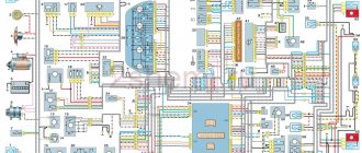
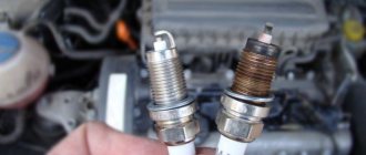
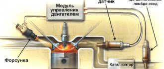
The proposed decoding schemes will help you in servicing the VAZ 21124 car. In a variant version, cars with VAZ-21114 and VAZ-21124 engines can be equipped with a starter and headlights manufactured by Bosch, fog lights, an instrument cluster with a liquid crystal display indicating the total and daily mileage, on-board computer, power windows in the front or all doors, power door locks and heated front seats. The engine power supply systems of the specified car do not have a fuel return line. The electric fuel pump module is installed in the fuel tank and includes the electric fuel pump, strainer, intake chamber, fuel pressure regulator and fuel gauge sensor. Connection diagram of the VAZ-21124 engine control system with distributed fuel injection under Euro-2 toxicity standards (controller M7.9.7) and electrical connection diagram of the 21124 Euro-3 engine control system. The description of the circuit elements is the same for both options.
1 – ignition coils 2 – injectors 3 – controller 4 – main relay 5 – fuse connected to the main relay 6 – cooling system electric fan relay 7 – fuse connected to the cooling system electric fan relay 8 – electric fuel pump relay 9 – fuse connected to electric fuel pump relay 10 – mass flow and air temperature sensor 11 – throttle position sensor 12 – coolant temperature sensor 13 – canister purge solenoid valve 14 – oxygen sensor 15 – knock sensor 16 – crankshaft position sensor 17 – idle speed control 18 – immobilizer control unit 19 – immobilizer status indicator 20 – phase sensor 21 – vehicle speed sensor 22 – electric fuel pump module with fuel level sensor 23 – oil pressure warning lamp sensor 24 – coolant temperature indicator sensor
A – block connected to the wiring harness of the ABS cabin group B – diagnostic block C – block connected to the air conditioner wiring harness D – to the “+” terminal of the battery D – to the side door wiring harness block E – block connected to the panel wiring harness devices
What are the VAZ 2110 fuse box relays responsible for?
K1 – relay for monitoring the health of light bulbs; K2 – front wiper relay; K3 – repeater and alarm relay; K4 – low beam relay; K5 – high beam relay; K6 – additional relay; K7 – relay for turning on the heated rear window; K8 – backup relay (not installed on 110 series vehicles);
F1-F20 in the diagram are fuses. The circuits in the car are protected by fuses based on a certain rated current (in A). The battery charging circuit, generator circuit, ignition and engine starting are exceptions.
To replace a faulty fuse, first find the one that has blown, then eliminate the reason why it was damaged and then install a new one. Below is a list of fuses and information on each one.
* Never replace fuses with jumpers, this can lead to failure of various components and elements, including failure of the wiring tracks in the fuse box and even a car fire.
Electromagnetic relays
To relieve the car switch contacts from high current consumption, electromagnetic relays are used in the electrical circuit. There are 8 of them in total:
- K1 is responsible for the serviceability of the lamps;
- for turning on the front window wiper - K2;
- for turn signals and hazard warning lights – K3;
- for low beam headlights - K4;
- for turning on the high beam - K5;
- for heating the rear window - K7;
- for fog lights located at the rear - K8.
The block contains relay K6, which is additional. Before installing a new element into the system, check the wiring for short circuits, otherwise the parting that is protected by the fuse element or the fuse itself may fail. The described block is the main one, but the only one in the VAZ-2112 electrical circuit.
To ensure safe and stable thermal conditions of an internal combustion engine, precise operation of the cooling system is required. The slightest failure will lead to overheating of the engine, which can lead to burnout of the head gasket or failure of the piston group elements.
The radiator fan is one of the key components of the car cooling system. Its role is to promptly force cool the liquid in the radiator. Problems with turning it on are a common occurrence for our cars.
In this article we will talk about possible reasons why the VAZ-2110 cooling fan does not work, and also consider options for eliminating them. But first, let's understand its design and operating principle.
Structurally, the radiator fan consists of:
An electric motor with an impeller on a shaft is installed inside a rectangular metal frame, with which it is attached to the back of the radiator. When voltage (12 V) is applied to the contacts of the drive, it begins to work, rotating the blades and creating a directed stream of air, which, in fact, cools the antifreeze or antifreeze.
The control of forced radiator airflow in carburetor and injection engines of the VAZ-2110 is significantly different. Firstly, the fan switch located on the radiator housing is responsible for everything. It is set to a certain coolant temperature. Usually this is 105-107 o C. When the coolant heats up to this temperature, the sensor is triggered, sending a signal to the fan relay. It closes the electrical circuit, driving the electric motor.
Turning on the cooling fan of a VAZ-2110 with an injection engine occurs somewhat differently. In engines equipped with an electronic control unit, there is no sensor on the radiator. Its place was taken by a temperature sensor located on the thermostat pipe. When the coolant heats up to a temperature of 105-107 o C, it sends a signal directly to the controller, which makes the decision to turn on the fan. It transmits an electrical impulse to a relay, which turns on the electric drive.
If the VAZ-2110 cooling fan does not work, do not rush to contact a car service center. You can determine the cause of the malfunction yourself. Moreover, it is not at all necessary to have special skills for this.
The cooling system fan may not turn on due to:
- electric drive malfunctions;
- blown fuse;
- faulty thermostat;
- a failed fan switch (temperature);
- faulty relay;
- broken electrical wiring;
- faulty expansion tank plug.
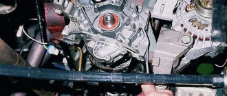
A common reason why the VAZ-2110 cooling fan does not work is a malfunction of its drive (electric motor). This may be wear of the brushes, breakage or short circuit of the windings, lack of contact in the connector, etc. It is not difficult to check the drive. To do this, simply disconnect the fan from the car's electrical circuit and connect it directly to the battery. If it does not turn on, the problem is definitely in it, but if the engine starts, you need to continue troubleshooting.
What are the fuses on the VAZ-2110 responsible for?
Decoding fuses.
License plate lamps. Instrument lighting lamps. Side light indicator lamp. Trunk light. Left side marker lamps
Left headlight (low beam)
Left headlight (high beam)
Right fog lamp
Door window motors
Portable lamp (socket)
Engine cooling fan electric motor. Sound signal
Rear window heating element. Relay (contacts) for turning on the heated rear window
Recirculation valve*. Windshield and headlight cleaners and washers ( wiper fuse ). Relay (coil) for turning on the rear window heating
Starboard side marker lamps
Right headlight (low beam)
Right headlight (high beam). High beam warning lamp
Left fog lamp
Electrically heated seats. Trunk lock lock
Relay-breaker for direction indicators and hazard warning lights (in hazard warning mode). Hazard warning lamp
Interior lighting lamp. Individual backlight lamp. Ignition switch illumination lamp. Brake light bulbs. Clock (or trip computer)
Glove box lighting lamp. Heater controller ( heater fuse ). Cigarette lighter fuse for VAZ 2110, VAZ 2111, VAZ 2112.
Locking door locks. Relay for monitoring the health of brake light lamps and side lights. Direction indicators with warning lamps. Reversing lamps. Generator excitation winding. On-board control system display unit*. Instrument cluster. Clock (or trip computer)
Rear fog lamps
Table of external connections and connectors of the VAZ-mounting block.
| Block | № | Color | Electrical circuits |
| Ш1 | 1 | ZhCh | fog lamp (left) |
| 2 | GP | trunk lock motor, heated seats | |
| 3 | R | door lock relay | |
| 4 | ABOUT | power window relay | |
| 5 | ZhP | fog light relay | |
| 6 | AND | fog lamp (right) | |
| 7 | MS | power window relay | |
| 8 | — | reserve | |
| Ш2 | 1 | — | reserve |
| 2 | — | reserve | |
| 3 | — | reserve | |
| 4 | H | weight " - " | |
| 5 | ZhP | size (left rear) | |
| 6 | Warhead | outdoor light switch | |
| 7 | — | reserve | |
| 8 | ZhCh | license plate lamps, off instrument lighting | |
| 9 | KP | size (right rear) | |
| 10 | TO | size (right) | |
| 11 | ZhG | email windshield wiper motor, windshield wiper and washer switch. | |
| 12 | Z | outdoor light switch | |
| 13 | ABOUT | fog light switch | |
| 14 | Emergency | hazard switch | |
| 15 | — | reserve | |
| 16 | GP | Ignition switch (terminal 15), steering column switch | |
| 17 | R | windshield wiper and washer switch | |
| 18 | JV | steering column headlight switch | |
| 19 | — | reserve | |
| 20 | — | reserve | |
| 21 | AND | size (left) | |
| Ш3 | 1 | midrange | low beam (left headlight) |
| 2 | — | reserve | |
| 3 | WITH | low beam (right headlight) | |
| 4 | R | generator (cl. 30) | |
| 5 | TO | generator (cl. 30) | |
| 6 | TO | generator (cl. 30) | |
| Ш4 | 1 | PZ | on-board display system |
| 2 | GO | hazard switch | |
| 3 | IF | hazard switch | |
| 4 | H | weight " - " | |
| 5 | PG | portable lamp plug | |
| 6 | Salary | heated rear window switch, heated rear window lamp | |
| 7 | — | reserve | |
| 8 | — | reserve | |
| 9 | — | reserve | |
| 10 | ZhZ | steering column washer and windshield wiper switch | |
| 11 | B | email windshield wiper motor | |
| 12 | BW | steering column washer and windshield wiper switch | |
| 13 | GB | steering column switch, ignition switch lamp | |
| 14 | BP | brake lights, clock, interior lamp | |
| 15 | P | brake lights | |
| 16 | RP | off brake lights | |
| 17 | ABOUT | generator (cl. 30) | |
| Ш5 | 1 | AF | high beam (left lamp) |
| 2 | JV | rear window heating element | |
| 3 | G | heater controller, glove compartment lamp | |
| 4 | Z | high beam (right lamp) | |
| 5 | ZhG | Windshield wiper motor, SAUO recirculation valve | |
| 6 | PB | email cooling fan, beep |
Circuits protected by additional fuses (all fuses are 15 A) on the VAZ-2110:
Additional fuses: 1 – ignition module, controller; 2 – canister purge valve, vehicle speed sensor, oxygen (heating) sensor, air flow sensor; 3 – fuel pump relay, fuel pump, injectors.
Additional relays: 4 – electric fan relay; 5 – electric fuel pump relay; 6 – main relay (ignition relay).
There is a fog lamp fuse installed in the niche of the instrument panel behind the mounting block:
Electrical diagram of the VAZ-21104 ECM with controller 21124-1411020-30/31/32
1 — block of the ignition coil wiring harness to the ignition system harness; 2 — block of the ignition system harness to the ignition coil wiring harness; 3 — ignition coils; 4 — immobilizer warning sensor; 5 — immobilizer control unit; 6 — spark plugs; 7 — nozzles; 8 — diagnostic block; 9 — block of the ignition system harness to the ABS cabin group harness; 10 - controller; 11 — electric fuel pump; 12 — block of the ignition system harness to the fuel level sensor harness; 13 — block of the fuel level sensor harness to the ignition system harness; 14 — block of the ignition system harness to the injector harness; 15 — injector harness block to the ignition system harness; 16 — block of the ignition system harness to the side door harness; 17 — speed sensor; 18 — idle speed regulator; 19 — throttle position sensor; 20 — coolant temperature sensor; 21 — mass air flow sensor; 22 — oil pressure warning lamp sensor; 23 - phase sensor; 24 — oxygen sensor; 25 — crankshaft position sensor; 26 — knock sensor; 27 — solenoid valve for purge of the adsorber; 28 — oil level sensor; 29 — coolant temperature indicator sensor; 30 — block of the ignition system harness to the instrument panel harness; 31 — block of the instrument panel harness to the ignition system harness; 32 — ignition relay; 33 - ignition relay fuse; 34 — fuse for the electric fuel pump power supply circuit; 35 — electric fuel pump relay; 36 — electric fan relay; 37 — controller power supply fuse; 38 — ignition system harness block to the air conditioner connector; 39 — instrument cluster; 40 — ignition switch; 41 — electric fan of the cooling system; 42 — on-board control system unit; 43 — starter relay; 44 — contacts of the 8-terminal blocks of the instrument panel harness and the front harness; 45 — contacts of the 21-terminal blocks of the instrument panel harness and the rear harness; 46 — trip computer; 47 - diagnostic connector.
Lada 2111 Agneska › Logbook › relays and fuses
The main fuses and relays on the VAZ-2110, 21102, 21103, 2112 are located on the left side of the steering wheel, just below. The figure shows the designations on the fuse mounting block/
Fuse number Current strength, A Circuits protected by fuse F1 5 Lamps for license plate lights. Instrument lighting lamps. Side light indicator lamp. Trunk light. Left side side light lamps F2 7.5 Left headlight (low beam) F3 10 Left headlight (high beam) F4 10 Right fog lamp F5 30 Door window electric motors F6 15 Portable lamp F7 20 Engine cooling fan electric motor. Sound signal F8 20 Rear window heating element. Relay (contacts) for turning on the heated rear window F9 20 Recirculation valve. Windshield and headlight cleaners and washers. Relay (winding) for turning on the heated rear window F10 20 Reserve F11 5 Side light bulbs on the right side F12 7.5 Right headlight (low beam) F13 10 Right headlight (high beam). Indicator lamp for turning on the high beam. F14 10 Left fog lamp F15 20 Electric seat heating. Trunk lock lock F16 10 Relay-interrupter for direction indicators and hazard warning lights (in hazard warning mode). Hazard warning lamp F17 7.5 Interior lighting lamp. Individual backlight lamp. Ignition switch illumination lamp. Brake light bulbs. Clock (or trip computer) F18 25 Glove box lighting lamp. Heater controller. Cigarette lighter F19 10 Door locking. Relay for monitoring the health of brake light lamps and side lights. Direction indicators with warning lamps. Reversing lamps. Generator excitation winding. On-board control system display unit. Instrument cluster. Clock (or trip computer) F20 7.5 Rear fog lamps
Operating principle of the fuse
Fuses are used in vehicles and are selected according to their rated load capacity. In the event of an emergency, when the voltage increases, the fuse link breaks and opens the electrical circuit.
The process of self-destruction starts in the event of:
- Short circuit - occurs if the insulation of conductive parts has been broken or the devices have been connected incorrectly. The problem of frayed insulation cables in a car is generally one of the most common causes of blown fuses.
- Incompatibility of the power of the consumer device and the rated current allowed for a specific electrical circuit. This problem is faced by those who decide to install additional electrical equipment (lighting, radios, etc.) in their car. Such powerful energy consumers are powered by basic wiring that is not designed to handle such high amounts of current. Due to excess current power, the wires melt and lead to a short circuit, which damages the fuses.
VAZ 2112 fuse box
If some devices on your VAZ 2112 car have stopped working, fuses or relays may be to blame. At the very least, the first thing you need to do is check them, and then draw some conclusions regarding the malfunctions. Correct diagnosis of many electrical problems will allow you to accurately determine the cause of the inoperability of a particular unit. To find out what fuses and relays do and how to find the right one, read this article.
Scheme
K1 – relay for monitoring the health of light bulbs; K2 – front wiper relay; K3 – repeater and alarm relay; K4 – low beam relay; K5 – high beam relay; K6 – additional relay; K7 – relay for turning on the heated rear window; K8 – backup relay (not installed on 110 series vehicles);
F1-F20 in the diagram are fuses. The circuits in the car are protected by fuses based on a certain rated current (in A). The battery charging circuit, generator circuit, ignition and engine starting are exceptions.
To replace a faulty fuse, first find the one that has blown, then eliminate the reason why it was damaged and then install a new one. Below is a list of fuses and information on each one.
What are fuses
Automotive fuses are an important part of the electrical circuit. They protect consumers from various malfunctions, and also protect wiring and the car as a whole from fires.
Let's say an inexperienced motorist is repairing a car. He forgot to disconnect the negative terminal of the battery before performing the work and during the repair he accidentally shorted the positive wire of some consumer to the ground of the car. A short circuit has occurred. At this moment, the current becomes maximum, and the conductor begins to heat up.
Such a phenomenon can damage the protected device, battery, or even cause a fire in the car. To prevent this, fuses are used. They look like this:
Additionally, fuses can shut down a circuit if a fault occurs.
Their color was not chosen by chance. It is a marking of the rated current for which this fuse is designed. If this rating is exceeded, the fuse inside it burns out. The denomination depends on the protected consumer or group of consumers.
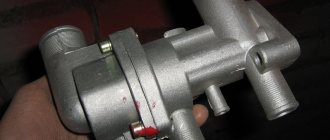
Where is the cooling fan relay on the VAZ-2110
In order for everything to work correctly in the VAZ-2110 engine, it is necessary to maintain a certain temperature.
This temperature range is achieved using a cooling fan, which, as a rule, comes with an electric drive. Its activation and deactivation is carried out automatically. Moreover, if the machine contains a carburetor engine, then TM 108 is used, and in the case when an injection engine is used, a controller is used. This article will tell you where the cooling fan relay is located on a VAZ-2110 car. If the fan is controlled by switching on, it is important that the temperature setting of the housing sensor is observed. The sensor is considered faulty when its temperature has reached the switch-on level, and the cooling motor has not worked. To check, you should close the contacts of the sensor, then check whether the fan works; if so, then the sensor needs to be replaced with a new one.
There are times when closing the contacts does not help and the fan still does not work, then according to the diagram, the integrity of the fuse with the supply wires is checked.
In order to start the cooling fan of the machine in which the injection engine is located, an electronic controller is used. Temperature conditions are pre-entered into the device software and range from 100 to 105 degrees. If the temperature sensor is faulty, then a system error is selected on the controller, and the cooling fan is activated when the car engine is turned on.
A number of breakdowns occur in which the controller does not detect the breakdown, and as a result, when the required temperature reaches 105 degrees, the fan simply does not start. To perform the test, remove the temperature sensor connector while the engine is running. If the system is working properly, the sensor will start the cooling fan, and by returning the connector to its original position, the fan will turn off. In case of damage to the circuit, check the quality of the relay, fuse and underwater wires. Everything must be installed exclusively according to the diagram. To carry out express checks, they bridge terminals 30 and 87 of the fan relay, which are located in the heating shaft. To make it easier to find, look in the passenger seat area.
When the fan is activated, connect the control lamp, the housing and output 86 of the relay, then the relay will operate and the fan will start automatically. At the same time, it is necessary to manipulate such a circuit only when the relay is located in the connector block. Here it is recommended to look at the controller and the wire, the relay connector with pin 46, if there is a breakdown in one of them. If a specific click of the relay did not occur, but a positive signal goes from the main relay to pin 85, or there was a click, but the cooling fan did not start, then this indicates a breakdown of the relay and the need to replace it.
Fuse threshold
From the above, it is clear that the fuse in the car is destroyed if the rated electricity value is exceeded. The fuse part overheats and burns out.
The rated current of the fuse is calculated using the formula: Inom=Pmax/U.
- Inom is the nominal current value, which is measured in Amperes;
- Pmax is the maximum possible load that a particular device can handle. Power is indicated on devices and measured in Watts;
- U is the network voltage level. This indicator is measured in Volts. The voltage level in the car network is 12 Volts.