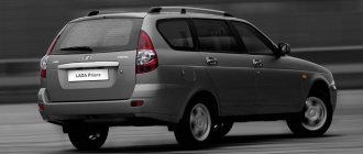
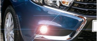
The VAZ 2104 with rear-wheel drive and a station wagon body was produced from 1983 to 2012. The model was constantly improved: electrical equipment was changed, a fuel injection system, a five-speed gearbox and semi-sports front seats appeared. The VAZ 21043 modification was supplemented with a system for cleaning and heating the rear door window. Information on the diagrams is intended for self-repair of cars. Electrical circuits are divided into several blocks for ease of viewing via a computer or phone; there are also files in the form of a single picture with a description of each element - for printing on a printer.
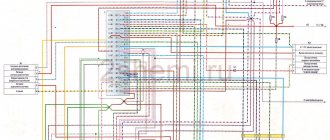
VAZ-2104 diagram (old version)
- block headlights;
- — side direction indicators;
- - accumulator battery;
- — starter activation relay;
- — carburetor electro-pneumatic valve;
- — carburetor microswitch;
- — generator 37.3701;
- — gearmotors for headlight cleaners;
- — electric motor of the engine cooling system fan*;
- — fan motor activation sensor*;
- — sound signals;
- — ignition distributor;
- - spark plug;
- — starter;
- — coolant temperature indicator sensor;
- — engine compartment lamp;
- — oil pressure warning lamp sensor;
- - ignition coil;
- — brake fluid level sensor;
- — gear motor for windshield wiper;
- — carburetor electro-pneumatic valve control unit;
- — electric motor of the headlight washer pump;
- — electric motor of the windshield washer pump;
- — brake light switch;
- — windshield wiper relay;
- — instrument lighting regulator;
- — relay-breaker for alarm and direction indicators;
- — reverse light switch;
- — plug socket for a portable lamp*;
- - cigarette lighter;
- — glove box lighting lamp;
- — mounting block;
- — lamp switches on the front door pillars;
- — lamp switches on the rear door pillars;
- - lampshades;
- — parking brake warning lamp switch;
- — switch for the carburetor air damper warning lamp;
- — tailgate glass cleaner and washer switch;
- - hazard warning switch;
- — three-lever switch;
- — ignition switch;
- - ignition relay;
- — external lighting switch;
- — rear fog light switch;
- — fog light circuit fuse;
- — oil pressure warning lamp;
- — instrument cluster;
- — fuel reserve warning lamp;
- — fuel level indicator;
- — courtesy light for the rear part of the cabin;
- — battery charge indicator lamp;
- — coolant temperature gauge;
- - carburetor air damper warning lamp;
- — parking brake warning lamp**;
- — block of warning lamps;
- — rear fog light indicator lamp;
- — control lamp for heated rear door glass;
- — brake fluid level warning lamp;
- - voltmeter;
- — speedometer 2104;
- — control lamp for external lighting;
- — turn signal indicator lamp;
- — high beam warning lamp;
- — heater fan switch;
- — heated tailgate glass switch with backlight;
- — heater fan electric motor;
- — additional resistor for the heater electric motor;
- — electric motor of the tailgate glass washer pump;
- — rear lights;
- — gearmotor for tailgate glass wiper;
- — pads for connecting to the rear glass heating element;
- — license plate lights;
- — sensor for level indicator and fuel reserve.
A
— headlight units, headlight and tailgate glass cleaners, windshield wiper relay-breaker, carburetor electro-pneumatic valve control unit;
b
- mounting block and three-lever switch;
c
— rear lights (pin numbering in order from top to bottom);
d
— relay-interrupter of the alarm and direction indicators.
Removing the instrument panel of a VAZ 2104
In order to begin work on changing the dashboard, work must be done to dismantle it. After removing the dashboard, perform the following work:
- We dismantle the devices and disassemble them, since only in this case can the installation of LEDs be carried out.
- Chrome rings around the perimeter act as a fixing element. You can bend the rings quite simply using a screwdriver.
- When bending the ring, it may be slightly damaged, but after assembling the structure this will not be visible.
- After the rings have been bent, they can be removed without much difficulty. The rings are made of soft material that is subject to mechanical stress.
- Once the chrome rings are removed, the glass, which acts as protection, can also be removed.
- On the back of the structure there are 2 nuts or screws that can be unscrewed and you can remove the device from their housing.
- After completing the above work, you can examine the visible part of the scale and black overlay. You can immediately notice that there is a small distance between them. This is where diodes can be placed to highlight basic information.
After the dismantling work has been completed, it will be possible to continue installing the LEDs.
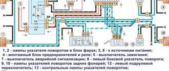
Electrical diagram of VAZ 2104
Scheme of VAZ-2104, for cars of early years of production. It is distinguished from the standard circuit by the G-222 generator, 10-pin hazard warning switch, 5-pin relay for direction indicators and hazard warning lights, top dead center sensor of the 1st cylinder, diagnostic block, rear window heating indicator lamp directly in the switch , the absence of a carburetor choke warning lamp, a two-position exterior lighting switch and a three-position steering column light switch.
1 — block headlights; 2 — side direction indicators; 3 - battery; 4 — battery charge warning lamp relay; 5 — carburetor electro-pneumatic valve; 6 — top dead center sensor of the 1st cylinder; 7 — carburetor microswitch; 8 — generator G-222; 9 — gearmotors for headlight cleaners*; 10 — electric motor of the engine cooling system fan*; 11 — fan motor activation sensor*; 12 — sound signals; 13 — ignition distributor; 14 — spark plugs; 15 - starter; 16 — coolant temperature indicator sensor; 17 — engine compartment lamp; 18 — oil pressure warning lamp sensor; 19 — ignition coil; 20 — brake fluid level sensor; 21 — windshield wiper gearmotor; 22 — carburetor electro-pneumatic valve control unit; 23 — electric motor of the headlight washer pump*; 24 — electric motor of the windshield washer pump; 25 — diagnostic block; 26 — brake light switch; 27 — windshield wiper relay; 28 — relay-interrupter for alarm and direction indicators; 29 — reverse light switch; 30 — plug socket for a portable lamp; 31 — cigarette lighter; 32 — glove box lighting lamp; 33 — mounting block (a jumper is installed instead of a short-circuit relay); 34 — lamp switches on the front door pillars; 35 — lamp switches on the rear door pillars; 36 — lampshades of VAZ 2104; 37 — parking brake warning lamp switch; 38 — rear window cleaner and washer switch*; 39 — alarm switch; 40 — three-lever switch; 41 — ignition switch; 42 — instrument lighting switch; 43 — external lighting switch; 44 — rear fog light switch; 45 — oil pressure warning lamp; 46 — instrument cluster; 47 — fuel reserve warning lamp; 48 — fuel level indicator; 49 — courtesy lamp for the rear part of the cabin; 50 — battery charge indicator lamp; 51 — coolant temperature indicator; 52 — relay-interrupter for the parking brake warning lamp; 53 — control lamp block; 54 — brake fluid level warning lamp; 55 — rear fog light indicator lamp; 56 — parking brake warning lamp; 57 - voltmeter; 58 — speedometer; 59 — control lamp for external lighting; 60 — turn signal indicator lamp; 61 — control lamp for high beam headlights; 62 — heater fan switch; 63 — rear window heating switch with control lamp*; 64 — heater fan electric motor; 65 — additional resistor of the heater electric motor; 66 — electric motor of the rear window washer pump; 67 — rear lights; 68 — rear window wiper gearmotor*; 69 — pads for connecting to the rear window heating element; 70 — license plate lights; 71 — sensor for level indicator and fuel reserve.
Electrical diagram - full view:
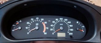
Instrument panel VAZ 21043 description
Controls and instruments (2105 instrument panel):
1 — side deflector of the ventilation system; 2 — headlight switch; 3 — direction indicator switch; 4 — sound signal switch; 5 — instrument panel; 6 — switch for cleaners and washers of the windshield and headlights (in a variant); 7 — cigarette lighter; 8 - switch for cleaner and washer glass of the trunk door of the car; 9 — control unit for the interior ventilation and heating system; 10 — glove box; 11 — window lifter handle; 12 — control knob for the external rear view mirror; 13 — armrest; 14 — internal door lock handle; 15 — storage shelf; 16 — seat belt lock; 17 — ashtray; 18 — parking brake lever; 19 — gear shift lever; 20 — heater cover lever; 21 — carburetor choke control handle; 22 — gas pedal; 23 — brake pedal; 24 — clutch pedal; 25 — hazard warning light switch (not visible in the photo); 26 — ignition switch (not visible in the photo); 27 — headlight hydraulic corrector handle; 28 — hood lock drive handle; 29 — instrument lighting control
The car is equipped with a model 2105 instrument panel. Some cars are equipped with a 2107 panel.
Controls and instruments (model 2107 instrument panel):
1 — side deflector of the ventilation system; 2 — headlight switch; 3 — direction indicator switch; 4 — sound signal switch; 5 — instrument cluster; 6 — handle for resetting the daily mileage counter; 7 — switch for cleaners and washers of the windshield and headlights (in a variant); 8 — switch for cleaner and washer of the tailgate glass; 9 — central deflectors of the ventilation system; 10 — control unit for the interior ventilation and heating system; 11 — glove box; 12 — control knob for the external rear view mirror; 13 — armrest; 14 — internal door lock handle; 15 — window lifter handle; 16 — storage shelf; 17 — ashtray; 18 — cigarette lighter; 19 — seat belt lock; 20 — parking brake lever; 21 — key switches; 22 — gear shift lever; 23 — hours; 24 — instrument backlight brightness control; 25 — gas pedal; 26 — heater cover lever; 27 — brake pedal; 28 — clutch pedal; 29 — hazard warning light switch (not visible in the photo); 30 — ignition switch; 31 — hood lock drive handle; 32 — headlight hydraulic corrector handle
| Control devices. 1. Thermistor; 2. Contact spring; 3. Cylinder head; 4. Paper insulating cartridge; 5. Sensor housing; 6. Sensor cover; 7. Pointer balancer; 8. Permanent magnet on the arrow axis; 9. Frame with pointer coils; 10. Device protection diode; 11. External lighting switch; 12. Oil pressure warning lamp; 13. Coolant temperature gauge; 14. Battery charge indicator lamp; 15. Warning lamp block; 16. Brake fluid level warning lamp; 17. Parking brake warning lamp; 18. Indicator lamp for turning on the fog light; 19. Speedometer; 20. Trip counter; 21. Rear window heating switch; 22. Plugs for screws securing the instrument panel; 23. Heater fan switch; 24. Indicator lamp for high beam headlights; 25. Turn signal indicator lamp; 26. Indicator lamp for external lighting; 27. Voltmeter; 28. Instrument cluster; 29. Fuel level indicator; 30. Fuel reserve indicator lamp; 31. Fog light switch in the rear lights; 32. Oil pressure sensor air filter; 33. Spring; 34. Movable contact of the sensor; 35. Fixed contact (connected to ground); 36. Diaphragm; 37. Cylinder block; 38. Fuel reserve alarm contact; 39. Sensor rheostat; 40. Movable rheostat contact; 41. Level indicator and fuel reserve sensor; 42. Lever with float; 43. Battery; 44. Generator; 45. Oil pressure warning lamp sensor; 46. Coolant temperature indicator sensor; 47. Brake fluid level sensor; 48. Mounting block; 49. Ignition switch; 50. Parking brake warning lamp relay; 51. Parking brake warning lamp switch; 52. I. Coolant temperature gauge; 53.II. Dashboard; 54.III. Oil pressure warning lamp; 55.IV. Fuel level indicator; 56. V. Electrical circuit for switching on control devices; |
On VAZ-2105 and VAZ-2104 cars, all control devices are located on the instrument panel. It contains: speedometer 19, voltmeter 27, block 15 of indicator lamps, instrument cluster 28, as well as four switches.
The instrument panel is attached to the instrument panel using two screws closed with plugs 22. To remove the panel to replace burnt out lamps or damaged devices, you need to remove the plugs 22 with a screwdriver, unscrew the screws and carefully remove the instrument panel from the instrument panel socket. When stopping the shield in place, it is necessary to avoid sharp bends of the flexible speedometer drive shaft, leading to residual deformation of the shaft shell. The bending radii of the shaft in the mounted state must be at least 100 mm.
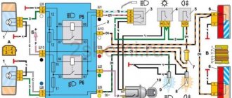
Scheme of VAZ-21043 and VAZ-21047 carburetor
1 — block headlights; 2 — side direction indicators; 3 - battery; 4 — starter activation relay; 5 — carburetor electro-pneumatic valve; 6 — carburetor microswitch; 7 - generator 37.3701; 8 — gearmotors for headlight cleaners*; 9 — electric motor of the engine cooling system fan; 10 — fan motor activation sensor; 11 — sound signals; 12 — ignition distributor; 13 — spark plugs; 14 — VAZ 21047 starter; 15 — coolant temperature indicator sensor; 16 — engine compartment lamp; 17 — low oil pressure indicator sensor; 18 — ignition coil; 19 — low brake fluid level indicator sensor; 20 — windshield wiper gearmotor; 21 — carburetor electro-pneumatic valve control unit; 22 — electric motor of the headlight washer pump*; 23 — electric motor of the windshield washer pump; 24 — reverse light switch; 25 — brake signal switch; 26 — hazard warning and direction indicator relay; 27 — windshield wiper relay; 28 — mounting block; 29 — lamp switches on the front door pillars; 30 — lamp switches on the rear door pillars; 31 — diode for checking the serviceability of the warning lamp for insufficient brake fluid level; 32 — lampshades; 33 — parking brake warning switch; 34 — indicator lamp for insufficient brake fluid level; 35 — signaling unit; 36 — plug socket for a portable lamp**; 37 — glove box lighting lamp; 38 — tailgate glass cleaner and washer switch; 39 — alarm switch; 40 — three-lever switch; 41 — ignition switch; 42 — ignition relay; 43—econometer; 44 — instrument cluster; 45 — carburetor air damper closed indicator switch; 46 — battery charge indicator lamp; 47 — indicator lamp for closing the carburetor air damper; 48 — indicator lamp for turning on the direction indicators; 49 — speedometer; 50 — fuel reserve indicator lamp; 51 — fuel level indicator; 52 — instrument lighting regulator; 53 — clock; 54 — cigarette lighter; 55 - fog light circuit fuse; 56 — heater fan electric motor; 57 — additional resistor of the heater electric motor; 58 — electric motor of the tailgate glass washer pump; 59 — rear fog light switch with on indicator; 60 — heater fan switch; 61 — switch for heating the glass of the tailgate with a switch-on indicator; 62-external lighting switch; 63 - voltmeter; 64-lamp indicator for turning on external lighting; 65-lamp for high beam headlights; 66 — low oil pressure indicator lamp; 67 — parking brake indicator lamp; 68 — tachometer; 69 — coolant temperature indicator; 70 — rear lights; 71 — pads for connecting to the heating element of the rear door glass; 72 — sensor for level indicator and fuel reserve; 73 — courtesy lamp for the rear part of the cabin; 74 — license plate lights; 75 — gear motor for tailgate glass cleaner.
Useful: VAZ-2113 diagram
Electrical diagram - full view:
Electrical supply diagram
These are the main components of the VAZ-2104 power supply system.
Its full diagram is presented below:
| 1 | Block headlights (includes low and high beam lamps, front dimensions) | 40 | Lamp switches (in door pillars) |
| 2 | Side turn signals (located on the fenders) | 41 | Body interior lamp |
| 3 | battery | 42 | Rear window heating switch with indicator light |
| 4 | Starter relay | 43 | Handbrake control |
| 5 | Electro-pneumatic carburetor valve (idle speed) | 44 | Rear PTF activation control |
| 6 | TDC sensor of the first cylinder | 45 | Checking the brake fluid level |
| 7 | Starter | 46 | Switch for washing and cleaning the rear window |
| 8 | Carburetor microswitch | 47 | Hazard switch |
| 9 | Electric motors for headlight cleaners | 48 | Handbrake control relay breaker |
| 10 | Generator | 49 | Turn signal switch |
| 11 | Sound signals | 50 | Headlight switch |
| 12 | Candles; | 51 | Horn switch |
| 13 | Engine compartment lamp | 52 | Switch for washing and cleaning glass and headlights |
| 14 | Coolant temperature sensor | 53 | Warning lamp block |
| 15 | Oil pressure lamp sensor | 54 | Switch for washing and cleaning glass and headlights |
| 16 | Distributor-breaker | 55 | Egnition lock |
| 17 | Windshield washer motor | 56 | Instrument panel lighting switch |
| 18 | Coil | 57 | PTF switch in the rear headlights |
| 19 | Brake fluid level sensor | 58 | Coolant temperature indicator |
| 20 | Headlight washer motors | 59 | Dashboard |
| 21 | Pneumatic valve control unit | 60 | Oil pressure check |
| 22 | Diagnostic block | 61 | Gasoline level indicator with reserve control |
| 23 | Windshield wiper relay | 62 | Battery charge control |
| 24 | Turn signal and emergency flasher relay; | 63 | Voltmeter |
| 25 | Window cleaning system motor; | 64 | Speedometer |
| 26 | Socket for connecting a portable lamp; | 65 | Checking side lights |
| 27 | Brake light switch | 66 | Turn signal control |
| 28 | Engine with interior heating | 67 | High beam control |
| 29 | Heating motor resistor | 68 | Dashboard light bulb |
| 30 | Handbrake warning lamp switch | 69 | Engine switch with ventilation and heating |
| 31 | Reverse light switch | 70 | Rear window washer motor |
| 32 | Mounting block | 71 | Rear block lights |
| 33 | Low beam relay | 72 | License plate lights |
| 34 | High beam relay | 73 | Rear window heating element |
| 35 | Jumper (instead of horn relay) | 74 | Rear window wiper motor |
| 36 | Relay for turning on the headlight washer and cleaning system | 75 | Luggage compartment lamp |
| 37 | Heated rear window relay | 76 | Gasoline level and reserve sensor |
| 38 | Glove box light | 77 | Ignition relay |
| 39 | Cigarette lighter |
Note that initially only export models of the VAZ-2104 were equipped with this electrical equipment system. It became standard for the subsequent modification of the station wagon - 21043.
For comparison, below is a diagram of the electrical equipment of the VAZ-2105, which was standard for the first station wagon models:
The diagram shows that the first station wagons were not equipped with a rear window heating and cleaning system, headlight washers and cleaners, as well as their control mechanisms. The rest of the electrical circuit is identical.
The electrical circuit of the VAZ-2104 injector is different in that this car already uses electrical equipment borrowed from the VAZ-2107 injection model. This modification of the station wagon was designated VAZ-21047 and it was the last in the history of this car.
Scheme for VAZ-2104 injector
1 – electric motor of the engine cooling system fan; 2 – mounting block; 3 – idle speed regulator; 4 – electronic control unit; 5 – octane potentiometer; 6 – spark plugs; 7 – ignition module; 8 – crankshaft position sensor; 9 – electric fuel pump with fuel level sensor; 10 – tachometer; 11 – control lamp “CHECK ENGINE”; 12 – car ignition relay; 13 – speed sensor; 14 – diagnostic block; 15 – nozzle; 16 – adsorber purge valve; 17, 18, 19 – injection system fuses; 20 – ignition relay for the injection system; 21 – relay for turning on the electric fuel pump; 22 – intake pipe electric heater relay; 23 – electric heater of the intake pipe; 24 – intake pipe heater fuse; 25 – oxygen concentration sensor; 26 – coolant temperature sensor; 27 – throttle position sensor; 28 – air temperature sensor; 29 – absolute pressure sensor;
- A – to the “plus” terminal of the battery;
- B – to terminal “15” of the ignition switch;
- P4 – relay for turning on the fan motor.
Brake system VAZ 2104
- Brake fluid level sensor built into the expansion tank cap;
- Electronic mounting block in the engine compartment with terminal “A” to the generator;
- Ignition relay with negative terminal to ground;
- Ignition switch on the steering column;
- Indicator lamp on the instrument panel indicating low brake fluid level;
- Indicator lamp for activated parking brake.
What is needed to carry out work on changing the dashboard?
As previously noted, in this case we will consider a budget method of changing the dashboard. To perform the work you will need diode bulbs that are blue. When choosing them, you should pay attention to the following points:
- LEDs that are shaped like a funnel are most suitable for changing the design. This is due to the fact that this type of lens scatters light best throughout the structure.
- The blue color was chosen because such light creates a rather interesting effect - it seems that we are looking at a dashboard that is used on a foreign car. For example, white diodes do not create a similar effect.
At the same time, we note that for the dashboard you will need one small diode for small instruments, and for large ones, for example, a tachometer and a speedometer, you will need 4 standard diodes and one diode lamp. The diode lamp is quite large, but it is necessary to increase the readability of all information.
Engine Fan Circuits
Scheme for switching on headlights and fog lights
1 — block headlights; 2 — mounting block 2104; 3 — headlight switch in a three-lever switch; 4 — external lighting switch; 5 — rear fog light switch; 6 — rear lights; 7 - rear fog light circuit fuse; 8 — fog light indicator lamp, located in the indicator lamp block; 9 — indicator lamp for high beam headlights, located in the speedometer; 10 — ignition switch; P5 - headlight high beam relay; P6 - low beam headlight relay; A - view of the headlight plug connector: 1 - low beam plug; 2 — high beam plug; 3 — ground plug; 4 — side light plug; B - to terminal 30 of the generator; B — terminals of the rear light printed circuit board (numbering of terminals from the edge of the board): 1 — to ground; 2 — to the brake light lamp; 3 — to the side light lamp; 4 — to the fog light lamp; 5 — to the reversing light lamp; 6 - to the turn signal lamp.
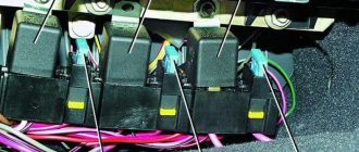
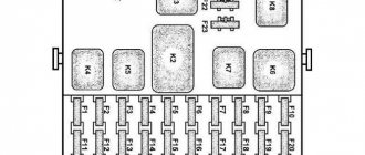
Fuse and relay block VAZ-2104
On newer “sevens” a block with 17 fuses and 6 relays is installed. VAZ 2107 fuses on the “new” unit protect the following electrical circuits and devices:
- Reversing lamps, heater fan, rear window defroster warning lamp and relay, rear wiper motor and rear washer pump.
- Electric motor for front wipers.
- Reserve socket.
- Reserve socket.
- Power supply for heated rear window.
- Clock, cigarette lighter, power socket “carrying”.
- Signal and radiator fan.
- Turn signal lamps in emergency mode.
- “Fog lights” and a relay that regulates the voltage of the on-board network.
- Instrument panel lamps.
- Brake light bulbs.
- Right high beam headlight.
- Left high beam headlight, high beam warning lamp.
- Side lights (rear right, front left), license plate and engine compartment lighting.
- Side lights (rear left, front right), glove compartment and cigarette lighter lamps.
- Low beam (right lamp).
- Low beam (left lamp).
The block relays perform the following functions:
- Heated rear window relay.
- Headlight cleaner and washer relay.
- Signal relay.
- Cooling system electric fan relay.
- High beam relay.
- Low beam relay.
Car modifications
VAZ-2104 . The basic version of the station wagon, with a carburetor engine from the VAZ-2105, 1.3 liters and 64 horsepower. Equipped with a 4-speed gearbox.
VAZ-21041 . A prototype of a station wagon, it was equipped with a carburetor engine from a VAZ-2101, with a volume of 1.2 liters and a power of 62 hp. Just like the base model, it was equipped with a 4-speed manual transmission.
VAZ-21042 . Export version, the steering wheel was located on the right. The car also received a carburetor engine from the VAZ-2103, with a volume of 1.5 liters and a power of 72 hp.
VAZ-21043 . The car was equipped with electrics and interior from a VAZ-2107, some copies had a VAZ-2106 interior. The carburetor engine was borrowed from the VAZ-2103. The gearbox was either 4 or 5 speed.
VAZ-21044 . An export model, equipped with a 1.7-liter VAZ-2107 engine with mono-injection, as well as a 5-speed gearbox.
VAZ-21045 . The export version with a 1.8-liter engine did not enter mass production.
VAZ-21045D . It was produced in small series since 1999, equipped with a VAZ-341 diesel engine with a volume of 1.52 liters and a power of 50 horsepower. The gearbox is 5-speed.
VAZ-21047 . A prototype with an engine starting from a penny. An improved version of the Four, it was equipped with a VAZ-2107 interior and a VAZ-2103 carburetor engine with a volume of 1.5 liters and a power of 72 hp. The gearbox was 5-speed. On export versions, the radiator grille was installed from the VAZ-2107.
VAZ-21048 . Diesel station wagon, with a 1.77-liter VAZ-343 engine. The gearbox is 5-speed.
VAZ-21041i . A car equipped with a VAZ-21067 injection engine. volume 1.6 liters. The gearbox is 5-speed. The electrical equipment and interior are from a VAZ-2107 car, and the front seats are from the Izhevsk hatchback IZH-2126.
VAZ-21041 VF . The interior, electrics and front seats are the same as the previous modification; the radiator grille is also borrowed from the VAZ-2107. It was equipped with a 1.5 liter injection engine from the VAZ-2103 and a 5-speed manual transmission.
Why the tachometer 2107 does not work
The VAZ-2107 can have two types of engines: carburetor and injection. The electrical circuit for connecting tachometers in these cars is different from each other, and they are not interchangeable. Therefore, troubleshooting related to tachometer failure will differ depending on the engine type.
On a carburetor engine, three wires come from the tachometer. Two wires are the power (plus and minus), and the third is connected to terminal K of the ignition coil. In order to find out what caused the failure, you need to get to the back of the instrument cluster and disconnect the terminals from the block that goes to the tachometer. Next, you will need three wires to connect the tachometer directly to the battery (plus and minus) and to the ignition coil (terminal K). You start the engine, and if under such conditions the tachometer does not work, then the problem will have to be looked for either in the ignition system or in the tachometer itself, and if the tachometer starts working, then the fault lies in the wiring that goes to the tachometer.