Do-it-yourself diagnostics
Various breakdowns of sensors and other devices can cause increased gasoline consumption, incorrect engine operation, and increased wear of car system components. Despite the presence of errors, the VAZ Priora will drive until the driver has to make expensive repairs because of them.
VAZ Priora car
So that the motorist does not suddenly have to face the need for repairs, a special controller is installed on the VAZ Priora, with the help of which the driver can diagnose breakdowns. This can be done either using special additional equipment or an on-board computer installed in the car.
In fact, to carry out diagnostics, the car owner will only need to press a few buttons and count combinations of faults.
For example, you do not have a special tester, so we will look at diagnosing the vehicle for errors using the on-board computer. The BC is built into the dashboard and can be used to read combinations of faults. To do this, you need to activate the auto test mode.
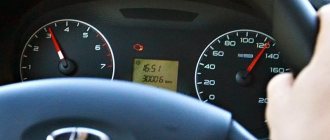
The arrows on the dashboard move to maximum values when performing self-diagnosis of the vehicle
- First, turn off the ignition. After this, hold down the daily mileage reset button and turn on the ignition. Please note: the button must be held down.
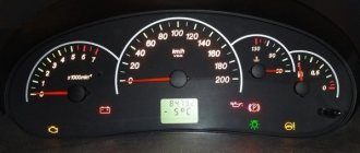
- There is an LCD indicator on the vehicle's dashboard, keep an eye on it. When you turn on the ignition, all icons will begin to light up, and all arrows (speedometer, tachometer, antifreeze temperature sensor, gasoline level status) will begin to move to the maximum values and back. That is, if all the arrows behave as described here, this means that the sensors and indicators are functioning correctly.
- Now you need to find the button for switching BC functions - it is located on the right steering column switch. By clicking on it, the software version (1.0 and higher) will be displayed on the screen.
- Click on this button again. Combinations of faults will begin to appear on the screen. If necessary, you can reset error data here. To do this, press and hold the daily mileage reset button for about three seconds.
The appearance of a fault combination on the LCD screen during self-diagnosis
Diagnostics of VAZ (LADA) before purchase
Is it advisable to buy a car that may actually turn out to be a shapeshifter? Does it make sense to put your hard-earned capital at risk? With all this, you probably have been saving money for a decent car for more than one year. Just contact us and we will diagnose the LADA car before purchasing at the point of sale with the seller. You will undoubtedly know that you received a quality car in every respect.
We have extensive experience, the necessary technical documentation and new computer programs for testing, as well as circuit diagrams of any cars, thanks to this our auto electricians can expertly repair faults of all models of VAZ (LADA) cars:
VAZ 2101, VAZ 2102, VAZ 2103, VAZ 2104, VAZ 2105, VAZ 2106, VAZ 2107, VAZ 2108, VAZ 2109, VAZ 21099, VAZ 2110, VAZ 2111, VAZ 2112, VAZ 2113, VAZ 2114, VAZ 2115, Lada Priora , Lada Kalina, Lada Lagrus, Lada Granta, Lada Vesta
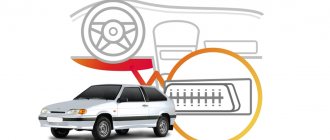
Diagnostic connector for Lada Priora
Modern cars, in the event of malfunctions in the operation of the engine or its systems, store errors in the memory of the electronic control unit (ECU). There is a special connector to connect it to diagnostic equipment in the car. The Lada Priora uses a standard European OBD-II connector.
Diagnostic connector Lada Priora OBD 2
Diagnostic connector location
Diagnostic connector location
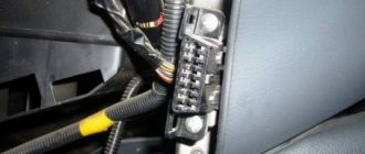
On Lada Priora cars, the diagnostic connector is located behind the glove compartment (glove box) on the rear wall on the left side. To gain access to the connector, open the glove compartment. Then disengage the glove box latches and lower it down.
Assignment of diagnostic block contacts
Assignment of diagnostic block contacts: 2 - J1850 Bus 4 - Chassis Ground 5 - Signal Ground 6 - CAN High (J-2284) 7 - ISO 9141-2 K Line 14 - CAN Low (J-2284) 15 - ISO 9141-2 L Line 16 - Battery Power
After reading the error codes, they are deciphered using the table:
Kalina/Priora on-board computer errors:
0102 Low level of mass air flow sensor signal 0103 High level of mass air flow sensor signal 0112 Low level of intake air temperature sensor 0113 High level of intake air temperature sensor 0115 Incorrect signal of coolant temperature sensor 0116 Incorrect signal of coolant temperature sensor 0117 Low level of temperature sensor coolant 0118 Coolant temperature sensor signal high 0122 Throttle position sensor signal low 0123 Throttle position sensor signal high 0130 Oxygen sensor signal 1 incorrect 0131 Oxygen sensor signal low 1 0132 Crankshaft sensor signal high 1 0133 Slow response oxygen sensor 1 0134 No signal from oxygen sensor 1 0135 Malfunction of oxygen sensor 1 heater 0136 Short circuit to ground of oxygen sensor 2 0137 Low level of oxygen sensor 2 0138 High level of high signal of oxygen sensor 2 0140 Open circuit of oxygen sensor 2 0141 Malfunction of oxygen sensor 2 heater 0171 Too lean mixture 0172 Mixture too rich 0201 Injector 1 control circuit open 0202 Injector 2 control circuit open 0203 Injector 3 control circuit open 0204 Injector 4 control circuit open 0261 Injector 1 circuit short to ground 0264 Injector 2 circuit short to ground 0267 Injector circuit short to ground sunki 3 0270 Short to ground in the injector 4 circuit 0262 Short to 12V in the injector 1 circuit 0265 Short to 12V in the injector 2 circuit 0268 Short to 12V in the injector 3 circuit 0271 Short to 12V in the injector 4 circuit 0300 Many misfires 0301 Misfires in cylinder 1 0302 Misfire in cylinder 2 cylinder 0303 Misfire in cylinder 3 0304 Misfire in cylinder 4 0325 Open circuit of knock sensor 0327 Low level of knock sensor signal 0328 High level of knock sensor signal 0335 Incorrect crankshaft position sensor signal 0336 Crankshaft position sensor signal error 0340 Phase sensor error 0342 Neither low signal level phase sensor 0343 High signal level of the phase sensor 0422 Low efficiency of the converter 0443 Malfunction of the canister purge valve circuit 0444 Short circuit or break in the canister purge valve 0445 Short to ground of the canister purge valve 0480 Malfunction of the cooling fan circuit 1 0500 Incorrect speed sensor signal 0501 Not correct speed sensor signal 0503 Interrupt speed sensor signal 0505 Idle speed control error 0506 Low idle speed 0507 High idle speed 0560 Incorrect on-board power supply voltage 0562 Low on-board power supply voltage 0563 High on-board power supply voltage 0601 ROM error 0603 External RAM error 0604 Internal RAM error 0607 Knock Channel Malfunction 1102 Low Oxygen Sensor Heater Resistance 1115 Faulty Oxygen Sensor Heater Circuit 1123 Rich Idle 1124 Lean Idle 1127 Rich Partial Load 1128 Lean Partial Load 1135 Oxygen Sensor Heater Circuit 1 open, short circuit 1136 Rich mixture in Light Load mode 1137 Lean mixture in Light Load mode 1140 Measured load differs from calculation 1171 CO potentiometer low level 1172 Potentiometer CO level high 1386 Knock channel test error 1410 Canister purge valve control circuit short circuit to 12V 1425 AD purge valve control circuit sorber short short to ground 1426 Control circuit of the canister purge valve open 1500 Open circuit of the control circuit of the fuel pump relay 1501 Short to ground of the control circuit of the fuel pump relay 1502 Short circuit to 12V of the control circuit of the fuel pump relay 1509 Overload of the control circuit of the idle speed regulator 1513 Circuit of the idle speed regulator short circuit to ground 1514 Idle air control circuit short circuit to 12V, open 1541 Fuel pump relay control circuit open 1570 Incorrect APS signal 1600 No communication with APS 1602 Loss of on-board voltage to the ECU 1603 EEPROM error 1606 Rough road sensor incorrect signal 1616 Rough road sensor low signal 1612 Reset error ECU 1617 Rough road sensor high signal 1620 EPROM error 1621 RAM error 1622 EPROM error 1640 EEPROM Test error 1689 Incorrect error codes 0337 Crankshaft position sensor, short to ground 0338 Crankshaft position sensor, open circuit 0441 Air flow through the valve is incorrect 0 481 Cooling fan circuit malfunction 2 0615 Starter relay circuit open 0616 Starter relay circuit short circuit to ground 0617 Starter relay circuit short circuit to 12V 1141 Malfunction of the oxygen sensor 1 heater after the converter 230 Malfunction of the fuel pump relay circuit 263 Malfunction of the injector driver 1 266 Malfunction of the force driver nki 2 269 Malfunction of injector driver 3 272 Injector driver fault 4 650 CheckEngine lamp circuit fault
Error code: Toyota Smart Keymaker - Elm327 Club online store
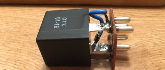
Priora tire can adapter
Adapter GF 921 is designed for connecting electronic instrument clusters that do not have a CAN bus (cars manufactured since July 2012). Installed on the Lada Priora family of cars (VAZ 2170-2171-2172)
The adapter is compatible with the following ECMs: BOSCH ME17.9.7;M72
An instruction manual is included in the kit.
Price when ordering in the online store.
If you live in Samara and want to purchase goods in an online store, then you will need to place an order by selecting the Delivery Method “Courier in Samara”.
The price at which the product is sold in a retail store at the address: Samara, st. Partizanskaya, 56a, shopping center "Cascade", office 206.
If the retail store price is not indicated, then the retail store sells the product at the online store price.
This is the status of the product, displaying information about the availability of the product in the warehouse.
This product is in stock at the store and will be sent to you as soon as possible without pre-ordering.
This item is currently out of stock, but we are awaiting availability from the manufacturer. Once the item arrives in the store, it will be shipped to you.
The operator will inform you when the goods arrive at the store.
This product is not in stock at the store, but we can bring it especially for you if you place an order.
Products supplied “to order” are shipped only with 100% prepayment.
The operator will inform you about the delivery time.
How to remove and check the sensor
Access from above to the Priora DD is difficult due to the intake module located above it. The easiest way to get to the sensor is from below, first removing the engine protection or at least unscrewing and folding its front part. When working from above, you will have to do everything by touch. In any case, before starting work, it is necessary to disconnect the ground wire attached to the “negative” terminal from the battery.
To remove the crankcase protection, you need to:
- unscrew 5 nuts with a 10mm head;
- unscrew the 2 19 nuts installed on the back of the shield;
- remove protection.
- by pressing the metal latch of the DD connector, disconnect the block of wires going to the controller;
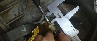
- using a 13mm wrench, loosen the bolt securing the sensor;
- Unscrew the bolt and remove it from the threaded hole, removing the sensor.
- We connect a multimeter to the DD terminals. We set the device to voltmeter mode, choosing a measurement limit of up to 200 mV.
- We take a metal object - pliers or a bolt - and lightly tap it on the DD.
When you tap on a working sensor, the voltmeter will show voltage surges. A faulty DD will not react in any way. A more accurate diagnosis of a removed sensor can only be done using a special stand.
Installation of a new DD is carried out in the reverse order of dismantling. Experts recommend installing a similar Bosch instead of the “native” one. Before going to the store for a new sensor, you should write down the markings of the removed sensor. Tightening the bolt securing it to 13 should be done with a slight force - 10.4–24.2 N m (1.1–2.5 kgf). Tightening too tightly will affect the operation of the sensor.
Problems with engine detonation can occur due to various faults. They are often associated with the operation of the electrical circuit from the knock sensor to the electronic control unit, or with the knock sensor itself. The diagnostic scanner can detect 4 common knock errors - P0325, P0326, P0327 and P0328.
Error code: Best application for obd 2 on android, iPhone
Test program activation
On Priora you can easily activate testing. This will help you recognize problems yourself and begin to solve them instantly. The test program allows you to solve common car problems, namely:
- fuel supply adjustment;
- searching for breakdowns in the transmission and neighboring structures;
- identify breakdowns and flaws in the firmware of the electronic control unit.
Brief conclusions
Owners of this brand should be aware of the location of the connector. This way you can be sure that you will always be able to identify problems in a timely manner. The main thing is to understand where this system is located and how to work with it.
Modern generation cars are equipped with a special electronic control unit, which is abbreviated as ECU. It is this unit that remembers any faults that may manifest themselves both in the car engine and in various electrical systems. To connect the unit to the equipment, a special connector is used for diagnostics. VAZ cars are equipped with a European standard OBD-II connector. Every VAZ owner must know where exactly the diagnostic connector is located in the Priora, unless, of course, he independently monitors the technical health of his car.
Lada Kalina 1 and 2 diagnostic connector location
The diagnostic connector is an indispensable attribute of the on-board engine control module in modern cars. Such a socket is also present in the domestic Lada Kalina. The main purpose of the diagnostic connector is to provide connection between the control unit (ECU) and an external reading device (scanner or laptop computer).
This allows owners (and not only Lada Kalina) to independently diagnose the on-board electronic system, as they say, “without leaving home.” Connecting a laptop (or other device) directly to the diagnostic connector is carried out using an adapter, then a specialized program is launched that reads error codes from the ECU memory.
Many car owners are interested in where this connector is located.
Let us repeat, to perform the diagnostic procedure in a Lada Kalina car you will need a set of the following tools:
- laptop or other scanning device;
- adapter (as a fashionable alternative today, owners use a “Bluetooth” connection);
- diagnostic software product.
Now you can find the vehicle's diagnostic connector. In the Lada Kalina, its location is in a very suitable place, close to the transmission lever. The socket itself is covered with a plastic cover, which has latches. In the second generation, Kalina has a diagnostic connector, which is located with its own cover, that is, you immediately connect and scan.
Having found the diagnostic connector, we connect it to the adapter. We carry out this manipulation with the ignition off. When the owner of a Lada Kalina uses a wired adapter, then its second edge, equipped with a “USB” connector, is connected to the corresponding socket in the laptop.
We launch the diagnostic software on the device. The program will require drivers. As a rule, they are sold together with the software package (on disk). We switch to the “establish connection” mode. After making sure that the switching has been successful, turn on the ignition and observe. The program begins the diagnostic process.
During the scanning procedure, the engine must be in idle mode. Now we compare each of the obtained parameters with the declared characteristics, which imply the normal functioning of the vehicle systems.
If discrepancies with standard values are observed by more than 20%, then all units or components that indicate such failures are subject to repair, and if this is not possible, replacement.
When the control unit detects an error, the “check engine” symbol lights up on the dashboard. Such a phenomenon should force the owner to perform a diagnostic action. Each error has its own code, the decoding of which can be found on a specialized website on the Internet. The software itself has a corresponding section where these errors can be viewed.
Therefore, when performing a check, we recommend that you carefully monitor deviations from the norm that appear in the functioning of the system.
When to change the timing belt on a Lada Granta 8 valve
Lada Granta timing belt replacement
Replacing the timing belt Lada Granta 8 valves
The diagnostic connector provides greater convenience to the Lada Kalina 2 maintenance process. Once scanning is complete, you can turn off the ignition. After that, in the software menu, select the “break connection” button and disconnect the adapter. The diagnostic procedure is now considered complete.
When you have figured out where the connector is located and connected to it, you can carry out diagnostics. Before the scanning procedure, it is necessary to visually inspect the main components of the car, and then assess their condition.
Diagnostics is aimed at identifying hidden faults in the operation of electronic systems. Using this option, you can evaluate the correct functioning of oxygen sensors, observe the operation of the control unit as a whole, identify and subsequently decipher error codes.
By the way, the errors themselves can be deleted after the diagnostic process is completed.
- Voltage level at the battery terminals (UACC). To check this indicator, you will need to simultaneously turn on all current collectors present in the car. The normal voltage value is at the level of 14-14.5 V. If this parameter is less than the specified value, then a thorough check of the electrical circuits will be required.
- Mass flow of air sucked into the Lada Kalina 2 engine (AIR). The verification process implies the presence of increased engine speeds (up to 5000 rpm). When, with such rotation of the crankshaft, the conventional indicator reaches 220-250 km per hour, the mass air flow sensor can be considered serviceable.
- Injection pulse duration (INJ). Here the discrepancy with the norm is checked in different operating modes of the engine. Idle speed is characterized by fluctuations in the parameter within 3-5 units, and for speeds close to maximum values - 15-20. If these limits are not met, then we are dealing with a problem.
- Oxygen level indicator (ALAM1). It is expressed in the electrical pulse equivalent generated by the corresponding sensor (“lambda”) and is 0.7 Volts. When the specified value is reached, it confirms the fact of stable feedback between the sensor and the unit.
- The number of “steps” generated by the Lada Kalina 2 idle speed regulator (FSM). This indicator reaches 40-60 pulses in idle mode and 150-180 during acceleration.
- Estimated fuel consumption (QT). The parameter contains a set of indicators, to read which you will need special equipment and a professional diagnostician. In independent mode, the owner can scan only one parameter - consumption per unit of time. For idle mode, the figure varies between 0.6-0.9 liters per hour.
How information is transmitted
So, the CAN bus is a network through which information is exchanged between devices. In practice this means the following. Let's take the engine control unit as an example - it has not only the main microcontroller, but also a CAN device that generates and sends pulses along the H (CAN-high) and L (CAN-low) buses, which are called twisted pair.
The signals are sent over a twisted pair cable by a transceiver or transceiver. It is needed for a number of tasks - amplifying signals, protecting the line in case of damage to the CAN bus, creating conditions for noise immunity of transmitted pulses and adjusting their transmission speed. In the automotive industry, two types of transmitters are used with the self-explanatory names High Speed and Fault Tolerant. The first provides data transfer at high speed, up to 1 megabit per second. The second one is not so fast and transmits up to 120 kilobits per second per second, but at the same time it is tolerant of errors, that is, it allows deviations from the parameters of the CAN bus and is not so sensitive to its quality.
Location
Often faced with a problem where the diagnostic connector is located. In each car they are installed differently, taking into account the specifics of the entire structure. As for Prior, everything here is done quite cleverly. If you don't know the exact location, it will be difficult to find.
Car manufacturers have placed a diagnostic connector in the glove box. You can find it on the passenger side in the interior. Simply put, look in the glove compartment. If you contact service centers, specialists will immediately find the required design. Beginners need to be more vigilant in this matter.
It is best to work according to already compiled instructions. Let's take a closer look at the process:
- We completely open the glove box and clear it of foreign objects to make it easier to work.
- The glove compartment should hang on plastic guides on each side.
- We press on the side plates so that the small door opens further. This will make it easier to work and find the Priora diagnostic connector.
- We pull out the tabs on the side and completely remove the glove box from the latches.
- Provides access to the input plug for diagnostics. Now he is free and ready to go.
Access to the device is open. The following operations directly depend on the purpose of “opening” your car. More often they get to the connector to reconnect it or check the correct signals from the ECU. This way his work will be adjusted and will not create problems or unforeseen situations.
Glove compartment in a Lada Priora car
How to install a can bus on a Priora
A modern car, unfortunately or fortunately - it’s up to you to decide, is no longer the same box on wheels, with a dozen and a half wires, which a more or less literate person could figure out and even fix if something was broken...
A modern car is already a computer on wheels, whether you want it or not... And even if you don’t suspect it, it’s only because professionals are repairing your car. They are the ones who should do all the work on your car. Accordingly, it is better to entrust the installation of additional equipment to specialists.
Often, when discussing issues of additional car security, you have to “lecture” clients, explaining, sometimes for a very long time, why their car alarm should be set not for 1 hour, but for at least 10 hours, and sometimes for one and a half to two days. And often in these conversations we have to mention such a phrase as “Kan shina”, which often confuses clients.
So what is CAN SHINA?
And why is it in the car?
First, the answer to the question - why? How to save copper? It is estimated that over the past five years the number of options in a car, which are mostly consumers of electrical energy, has doubled. And this happened not at all at the whim of automakers, but thanks to the growing needs of customers for comfort and legal requirements for safety and environmental protection
Pinout
Where is the diagnostic connector on the Granta fret? Knowledge of the pinout may be required if a car enthusiast wants to make an adapter for computer diagnostics with his own hands, or if you need to connect without it. Experts recommend buying ready-made devices without the need to make a plug yourself.
However, if you do not have such an opportunity, and diagnostics need to be carried out urgently, we will consider two main pinout options used on VAZ cars of various years of manufacture. Until 2002, AvtoVAZ products used the following pinout option:
- The 4th and 5th pins are GND outputs.
- 16th pin – 12 V (power line).
- The 7th contact is the diagnostic line itself.
Since 2002, the pinout scheme has changed significantly. Now it looks like this:
- Pin H – 12 V (power line).
- Contact G – 12 V for the fuel pump.
- Pin A – GND output.
- Contact M – diagnostic line.
There is one important note to note regarding this diagram. If you connect the connector without a block, but directly, it is recommended to use the charge from the cigarette lighter as a source of electricity
The peculiarity of this pinout is that contact H is not always routed in the car. The use of G is also not recommended because high frequency current is supplied. This can have a negative impact on the adapter, even to the point of burning it out.
As you can see, the pinout on VAZ cars of different ages is sometimes very different. Therefore, we advise you to look at the registration certificate of your car and find out what year it is made. On older vehicles you will not find the new pinout design as it did not exist yet and on newer vehicles the old design was no longer used.
Anti-theft protection for connector
The connector also helps thieves.
By connecting to it, the attacker can easily turn off the car alarm, and his further actions will be predictable. The whole problem is that the thief knows in advance the location of the plug, which simplifies his life, and connects to it immediately after opening the car door. The plans of attackers can be ruined if the diagnostic plug is moved to another place in the car. This is most often done at service stations, so it is recommended to entrust this operation to specialists. If you do this yourself, you should first think about where to put the plug so that it “does not catch your eye.”
In words, everything is quite simple: remove the plug, disconnect it, put it in a new place and reconnect the wire block. In fact, you will have to dig a fair amount into the inside of your Priora, but it’s worth it if you want to take care of protection against theft.
The diagnostic plug will make life easier for the owner of a Lada Priora - instead of torturing yourself with a tool in your hand, digging in the engine compartment, you just need to get this “adapter”, find out the reason and only then start repairing.
Deciphering error codes
The Lada Kalina has a diagnostic connector when equipped with a self-diagnosis system, which is now installed on almost all modern cars. The presence of such a connector in cars is due to stricter inspection rules during technical inspections.
Engine diagnostics are carried out to identify hidden problems and defects, as well as to assess the performance of each mechanism.
Diagnostics of Lada Kalina, which can be carried out using a connector.
Diagnosing a fuel-injected car just seems complicated and incomprehensible. Many people believe that this is a matter for trained and experienced craftsmen, but you can check the operation of control systems yourself.
Self-diagnosis begins by connecting the diagnostic tester to the vehicle controller. This makes it easy to obtain diagnostic data and errors. Instead of a tester, you can use a special program by downloading it for free on any suitable resource.
The adapter designed for the connector comes with a special driver and software. The COM port that appears in the program must be rearranged to numbers 1,2, 3 or 4. These are the numbers with which the standard Kalinovsky connector works.
Each engine has its own standard parameters. These are technical characteristics that determine the normal operation of the motor. These parameters are compared with the values obtained during diagnostics. All measurements are carried out with the engine running at idle speed.
But the engine may have malfunctions and malfunctions and not generate errors. For example, if the idle speed is too high, the control unit believes that the driver pressed the gas pedal, does not perceive the situation as an error and, naturally, does not display it during diagnostics.
- Battery voltage level (UACC). To carry out the test, it is necessary to turn on all the most powerful sources of energy consumption. If the voltage reading on the diagnostic screen is less than it should be, you will have to check all electrical circuits separately. Normal values are from 14 to 14.5 V.
- Mass air flow (AIR). The indicator is determined by the mass air flow sensor. Without diagnostic equipment, checking air flow is impossible. To obtain the value, you need to press the gas pedal until the speed is 5000. If the sensor is working, the indicator rises to a level of 200-250 kg/h.
- Injection pulse duration (INJ). This is the time fuel is injected into the cylinder while each injector is open. Indicators that exceed the norm indicate that the injectors are most likely clogged and clogged. To fix the problem, the parts should be washed. The reasons may also be a clogged fuel filter or a pump failure. To accurately diagnose the problem, press the gas pedal. Normally, the indicators should be from 3 to 5 in a calm, idle state and from 15 to 20 when gasping.
- Oxygen indicator before the catalyst (ALAM1). It should not exceed 0.7 V and, reaching this figure, go back down. This indicates that the feedback is working properly.
- Number of idle speed control (FSM) steps. In other words, the idle speed control sensor. It is a stepper electric motor with a cone-shaped plug attached to the shaft. When the engine is idling, this figure is 40-60 steps, when accelerating - from 150 to 180 steps.
- Estimated fuel consumption (QT). For a complete diagnosis, check the pressure in the fuel rail and the voltage in the spark plugs. It wouldn't hurt to check the compression on the cylinders and find out the CO. However, for all these measurements, in addition to the diagnostic connector and standard equipment, you will need another, expensive device and the connection of experienced professionals. Therefore, here you will have to limit yourself to one indicator: from 0.6 to 0.9 l/hour at idle.
- Throttle Position (THR) value. This parameter is determined by a special sensor. If the throttle position value shows an error and malfunction, the car owner may notice some jerks with “dips” while driving. An increase in the number of idle revolutions will also indicate the presence of a problem. This parameter should be checked with the ignition on, but it is not recommended to start the engine itself. When you gradually press the gas pedal, the readings on the monitor should smoothly increase to 90%. It should be taken into account that it is impossible to achieve 100% - this is predetermined by the manufacturers. The sensor is considered operational if the procedure was successful. Idle speed should show 0%.
- Crankshaft and its rotation frequency (FREQ). The diagnostic figure will be displayed on the screen by a special crankshaft position sensor. The malfunction is easy to notice even without diagnostic equipment, because the engine simply will not start. Indicators from the sensor normally vary in the range from 800 to 840 rpm.
- Limit of uneven crankshaft rotation (LUMS_W). This figure should not exceed 4 rpm. Otherwise, you can be sure that there are misfires in the cylinders. With such a malfunction, it’s time to check the spark plugs and high voltage wires.
- Ignition timing (UOZ). Data from several sensors are combined into one indicator and calculated by the electronic control unit. The value varies from 6 to 15.
- 2 - overvoltage;
- 3 - malfunction of the device indicating the fuel level;
- 4 — the cooling temperature sensor does not work, the circuit may be broken;
- 5 - outside temperature sensor error;
- 6 - probable motor overheating;
- 7 — emergency oil pressure level;
- 8 - the brake system is faulty;
- 9 — battery is discharged;
- E - the error is contained in the data packet.
Priora dashboard without bus
Welcome to ChipTuner Forum.
Theme Options
angryfly
It won’t work, on machines with firmware B547DD02 communication with the instrument cluster via CAN. On firmware B574DB03, the device is needed without CAN.
You can distinguish the devices by the last two digits of the instrument panel article number.
TFT "Priora" - 2170-71-72 produced before 06.2012 (without CAN bus)
Don’t ask me anything, I wrote everything I know.
You can copy this article to your blog, then notify me so that I can delete this entry.
First type of devices:
Kalinas and Prioras without can tires.
On the VAZ-1118 (Kalina) from 2004 to 2011, the device was installed 1118-3801010
All these devices have a 32-pin connector. You can, for example, install a Priorovskaya tidy instead of a Kalinovskaya one, but it is advisable to select the desired model (1118 or 2170).
Instead of such a tidy, you can install an expensive tidy with navigation 1118-3801010-50 for Kalina and 2112 with Europanel or 2170-3801010-50 s for Prior produced before July 2012 (without CAN bus). And they additionally need a GPS antenna and a wiper switch with a joystick (they are described below).
Addition from Shurik5891
On the first releases of 1118 devices, there are no LEDs for ABS, ESD, or seat belts.
Addition from Shandys
On Kalina1 2013 with e-gas and cable drive gearbox there is a tidy 11180-3801010-20 vdo _____________________________________ Second type of devices
Granta 1st generation
Granta appeared in 2011
From a smart book: “The electronic engine control system of the LADA GRANTA car implements a data exchange interface between the ECM, instrument cluster and diagnostic device via the CAN bus. The CAN bus is a two-wire line: - CAN L low level line (contact “X2/D2” of the ECM - contact “7” of the instrument cluster - contact “14” of the diagnostic block); - CAN H high level line (contact “X2/F1” of the ECM – contact “8” of the instrument cluster – contact “6” of the diagnostic block). The immobilizer is integrated into the instrument cluster." Pinout of devices 2190
Is it possible to move the diagnostic connector to another location?
The question often arises in the minds of motorists: can they choose another location for the AR or not? Is it possible to hold such an event on your own? Car owners are interested in this issue, since car thieves know where the DR is located, in particular on the Priora, and are easily able to disconnect it from the alarm. But if this element is installed in another place, then it is quite possible to complicate the theft procedure significantly. Therefore, in this way it will be possible to prevent a possible crime.
Let’s say right away: installing a diagnostic connector in another place in the Lada Priora is quite possible, but experienced specialists advise resorting to such a service at a service station. There, qualified employees will carry out the transfer of this part carefully and accurately.
So:
- carefully and accurately disconnect the wires from the connector;
- without haste, remove the device from the socket;
- move the diagnostic connector to the selected location;
- reconnect the connecting wires.
Attention! Experienced experts advise removing the connector yourself next to the gear shift knob or to the left of the steering column.
When another area for AR is selected and the planned manipulation is performed, only you are now aware of where exactly the connector is located. But, note, the hijackers will not be able to react in time to where the area of interest is located.
VAZ auto electrician on-site
The computer diagnostic service with on-site VAZ (LADA) cars in Moscow is in a hurry to provide immediate technical assistance in any difficult situation on the road. You don't have to waste valuable time moving your car to a car service center. A knowledgeable auto electrician and VAZ (LADA) diagnostician will come to your call point.
We provide roadside assistance and will be useful in:
- auto electrician visit
- repair of immobilizer of any manufacturers
- emergency car opening
- emergency door opening
- opening locks
- light the car
- charge the battery
- computer diagnostics
- troubleshooting
- delivery of gasoline to the site
- electrical repair
- eliminating found problems
- diagnostics of electrical equipment for heated windows
- checking the condition of the electrical wiring
- programming of car control and car alarm units (if necessary)
- replacing broken auto parts
- installation of additional electrical equipment
- It’s not clear, but something is wrong with the car
- other failure variations
Diagnostic process using a laptop
We will not describe the diagnostic procedure for each software separately, since in general, regardless of the software, this process is identical.
The general diagnostic procedure is described below:
- First, you need to install the software on your computer. If you know how to use the Internet, then this step will not cause you any problems, since there is nothing complicated in its implementation. If your adapter comes with a disk with drivers, then they must also be installed, otherwise the computer simply will not recognize the device.
- Then you need to open the cover in front of the gearshift lever or remove the protective trim on the right side of the center console, depending on the version of the car. You should obtain and ensure unobstructed access to the K-Line output to which you will connect the laptop.
- Next, take the purchased cable and connect it - one side to the computer, the other to the output.
- After the cable is connected, you need to make sure that the computer recognizes it, to do this, check for connection. Alternatively, to do this, you can go to the Windows Task Manager and go to the Hardware tab. If the operating system recognizes the device, this information should be noted in this tab.
- If the connection is successful, then you need to run the test program on the laptop. After launching, the utility should ask you which components you want to diagnose (transmission, engine, etc.). If this does not happen, then navigate the menu - there should be a “Start diagnostics” button somewhere, perhaps in the File menu. All existing faults will be shown in the table in the form of error codes.
- If you go to the Parameters tab, you can see how the general condition of the vehicle is described here. In the Codes tab, all faults identified by the diagnostics should be noted.
- All you have to do is decipher the resulting combinations of numbers and start troubleshooting. As practice shows, quite often during testing, sensor malfunctions pop up - usually such problems are caused by broken wiring or poor connection of controllers. Therefore, if you encounter this, do not rush to change the sensors - try to clean the contacts on the connection connectors, and also check the integrity of the wiring.
- After the faults have been eliminated, you need to reset the control unit memory to remove all error codes from it. You can reset the unit's memory through the diagnostic program - usually this function can be found in the Management section.
Video “How can you diagnose Kalina without a laptop?”
A less accurate, but simpler version of diagnosing Kalina without a laptop is presented in the video below (the author of the video is Igor T).
On a Kalina car, the diagnostic connector performs important functions. Almost all modern cars are equipped with an electronic control unit and a self-diagnosis system. It is a mini-computer programmed to perform certain functions. Tightening the rules for undergoing maintenance has led to the emergence of special devices. The Lada Kalina, equipped with electronic systems, also received a diagnostic connector.
Elm327 does not connect to the computer
- home
- » elm327 does not connect to the computer
Due to the increased number of low-quality adapters, if you are faced with the problem that your elm327 adapter does not connect to the car’s ECU, then most likely the problem is that you were sold an adapter with version 2.1 or version 1.5 converted from version 2.1. These adapters use a different Bluetooth module that supports only two protocols out of 6. This is why most often you get a connection with the adapter’s smartphone, but when you try to connect to the car’s ECU, the adapter writes that the ECU is not responding. Here is a short video on a visual comparison of the adapter versions.
If you have an elm327 adapter with an honest version 1.5 where all 6 out of 6 protocols are present, you can be helped by the initialization lines that help the device adapt to the commands of your car’s ECU.
Initialization lines for the Torque and HobDrive programs for cars using non-standard connection protocols. Currently, various diagnostic adapters designed to help the motorist diagnose his own car have become widely popular. The most popular adapters are the elm327 series, which support work with most foreign cars after 1996, as well as domestically produced cars. However, in practice, owners of certain car brands experience difficulties in connecting their car to a diagnostic program that refuses to communicate with the car's electronic control unit. The most common at the moment is the Torque program, so for example, when connecting this program to Japanese market cars produced for domestic use and not having full support for the OBD2 standard, the user is faced with the fact that the program cannot connect to the ECU. In such cases, when your car has a specific unit that one or another program refuses to work with, manually writing an initialization line for the program may come to your aid.
Each car brand uses its own initialization string, in this article we will present the most common initialization strings: - Toyota JDM Nadia/Harrier ATIB96 nATIIA13 nATSH8213F1 nATSPA5 nATSW00 - Toyota JDM 10400baud ATIB10 nATIIA13 nATSH8013F1 nATSPA4 nATSW00 - Toyota JDM CAN mode21 ATSP6 n ATAL nATSH7E0 nATCRA7E8 nATST32 nATSW00 — Toyota GT86 ATSP6 nATAL nATSH7E0 — Toyota JDM ISO9141 ATSP3 nATAL nATIIA33 nATIB10 nATSH686AF1 nATST32 nATSW00 — Toyota JDM Common ATIB96 nATIIA13 nATSH8113F1 nATSPA4 nATSW00 — Toyota Celica ZZT230 ATIB 96 n ATIIA 13 n ATSH 8113F1 n ATSP A4 n ATSW00 — Toyota Vitz 01.2002 ATSH8213F1 n ATIB96 n ATIIA13 — Fiat Pre-OBD ATSH 8110F1 — Nissan Custom ATSP5 nATAL nATIB10 nATSH8110FC nATST32 nATSW00 — Mitsubishi MUT ATSP0 nATAL nATIB10n — Tiggo Delphi MT20U ATSP5 nATAL nATIB10 nATSH8111F1 nATST32 nATSW00 — Delphi MR24 0 ATSP5 nATAL nATSH8111F1 nATWM8111F13E - Siemens ACR167 KWP ATSP5 nATAL nATSH8111F1 n81n - Sirius D42 ATSP5 nATAL nATIB10 nATSH8211f1 nATST32 nATSW00 nATFI - VAZ January ATSP5 nATAL nATIB10 nATSH8110F1 nATST32 nATSW00 - VAZ Bosch MP7 ATSP5 nATAL nATIB10 nATSH8111F1 nATST32 nATSW00 nATFI - VAZ Bosch 7.9.7 ATFI nATALn - UAZ ME17.9.7 ATSP5 nATAL nATSH8110F1 nATFI - Opel KWP2000 ATSP5 nATAL — Japan Domestic Market Nissan ATSP5 nATAL nATIB10 nATSH8110FC nATST32 nATSW00 — Japan Domestic Market Nadia / Harrier ATIB10 nATIIA13 nATSH8013F1 nATSPA4 nA TSW00 — January 5.1.1 ATSP5 nATIB10 nATSH8110F1 nATST10 nATSW00 — January 7. 2 Euro 2 atal natsp5 natib10 natsh8110f1 natst32 natsw00 natfi — VAZ Itelma/ Avtel M73 E3 ATSP5 nATAL nATSH8110F1 nATSW00 - UAZ Patriot Bosch m17.9.7 ATZ nATSP5 nATIB10 nATSH8110F1 nATSW00 - SsangYong 2.3 MSE petrol (Kyron, Rexton, Action, Musso, Korando) atsp5 natib10 natsh8101f3 natst32 n atsw00 — BYD F3 ATSP5 nATSH8111F1 nATSW00 — Toyota Passo KGC1 (1KR-FE) atsp5 natsh8110f0 natfi — Toyota Sienta with ABS atsp4 natal natib96 natiia29 natsh8129f1 natst32 natsw00 — ABS Lifan Solano (wanxiang) ATSP5 nATSH8128F1 nATWM8028F1021080 nATFI — OPEL Simtec 56.5 ATSP5 /nATSH8111F1 /nATSW00 — GREATWALL Delphi MT20U2_EOBD atal natib10 natsp5 natsh8111f1 natst10 natsw00
Error code: ELM327 bluetooth does not see the phone and does not connect - what to do