What are turn signal relays for?
A turn signal relay, also called a breaker relay, ensures that the turn signals operate correctly. Unlike other lighting devices, turn signals operate intermittently, that is, they blink. This ensures additional attention from others to the vehicle driver’s intention to perform a maneuver: change lanes, make a turn, etc.
The intermittent operation of the direction indicators is ensured by the breaker relay. It closes and opens the electrical circuit, causing the turn signal lamps to flash, attracting the attention of others. Also, the breaker relay additionally ensures the creation of an audible click, which reminds the driver of the car that the turn signal switch is on. And the last function of the turn signal relay is the operation of the hazard warning lights, so in modern cars the operation of the turn signals and emergency lights is provided by one relay.
The absence of blinking of the direction indicators is equivalent to their malfunction, so a breakdown of the relay will not allow the driver to pass the inspection. Also, incorrect operation of turn signals is regarded as a failure to comply with traffic regulations to warn other drivers about the maneuver and can lead to a fine from the traffic police in the amount of 500 rubles.
Turn signal diagram
Turn signals are very important in busy modern traffic, and malfunctions cause great inconvenience. The turn signal design on domestic and imported cars is almost the same. Depending on the year of manufacture of the car, electromagnetic-thermal or electronic relays are used as a breaker. The principle of connecting all relays is almost identical. Currently, some imported cars and VAZ 2170 Priora do not have a turn signal relay; its function is performed by an electronic control unit for power accessories. This article only discusses the classic turn signal design.
Consider a turn signal circuit using a relay. In these circuits, the relay is connected in series with the signal lamps through the turn switch. An exception is the connection diagram of the turn relay type RS 950 and its analogues used on trucks. We will return to the connection diagram for this relay a little later. First, let's look at the connection diagram for direction indicators with an electromagnetic-thermal relay of type RS 59. As can be seen from the figure, the diagram is very simple.
When the ignition is turned on, power is supplied to the turn relay, and when the turn switch is moved in one direction or another, the relay is connected through the signal lamps to the minus. In this case, when the relay contacts close, the lamps light up, and when they open, they go out. The use of an alarm system with this relay is not possible due to its heating during operation and rapid failure due to the high power consumed by the lamps. In addition, this relay will not work with diode lamps, since the current consumption of these lamps is not sufficient to close the contacts. The operation of such a relay is described in detail in the article “VAZ-2101 Turning Relay.” The following connection diagram with an electronic relay, except for the RS 950 type relay and its analogues. Electronic relays, as a rule, have from 3 to 5 pins, and their connection diagram is fundamentally identical to that described above. Since electronic relays allow switching large currents, unlike electromagnetic-thermal relays, it becomes possible to activate an alarm through them. To implement this, the circuit additionally includes an alarm button. The methods for enabling it on different cars may differ, but not significantly. In turn signal mode, power to the relay is supplied through the hazard warning button contacts from the ignition switch, and in hazard warning mode directly from the battery. Also, in the emergency mode, the button connects the output of the relay signal lamps with its contacts to the signal lamps, bypassing the turn switch. Connecting an electronic relay from an electromagnetic-thermal one differs only in the presence of a terminal connected to the vehicle ground.
The RS 950 type turn relay is included in the turn signal circuit before the turn switch, in contrast to a simple electronic relay. This is due to the way the control lamps are connected. A relay consists of an electronic part that controls an electromagnetic relay. When turning on one of the sides of the car, current pulses from the electromagnetic relay are supplied to the turn switch, then through the turns relay terminals, electromagnetic relay coils or warning lamp reed switches, they are supplied to the warning lamps. Below is a schematic diagram of connecting the relay.
admin 03/12/2013
“If you notice an error in the text, please highlight this place with the mouse and press CTRL+ENTER” “If the article was useful to you, share the link to it on social networks”
Work principles
The variety of turn relays is quite large, but they are all divided into two main types:
- classical electromagnetic-thermal relays;
- electronic relays.
Electromagnetic-thermal relays are considered obsolete and can now only be found on very old cars, for example, classic Zhiguli cars. This type of relay consists of a core with a copper winding. There are two contact groups in the upper part of the core, and metal anchors in the sides. The structure is placed in a metal case, in the lower part of which contacts for connecting to the network are output.
When the turn switch is turned on, the network is closed - the lamp does not light. Then one of the anchors, under the influence of the nichrome string in the core, straightens and closes the contacts. After this, the current begins to flow in a bypass circuit, and the lamp lights up at full power. The click of the turn signals is ensured by the impact of a metal armature on the contacts.
An electronic relay consists of two main parts: a classic electromagnetic relay and an electronic key that ensures the frequency of operation of the relay. In a relay of this type, the operating principle of the nichrome string, which ensures the closure of the contacts, is assigned to a separate circuit board (key). Otherwise, the operation scheme is similar: the flowing current closes the contacts, after which the indicator lamps and the light on the dashboard light up. Interruption of the current leads to lowering of the armature and opening of the contacts - the indicator lamps go out. A characteristic click is also provided by the impact of the armature on the contacts.
How does an electromagnetic-thermal relay work?
These devices are no longer used in modern cars. However, in older models they are still widely used.
The design of the electromagnetic-thermal relay is quite simple; it uses a circuit for connecting turn signals through an electromagnetic-type relay. It is made in the form of a cylindrical core, and a thin copper wire is used as its winding. At the top of the core there are two groups of contacts, and metal anchors are installed on each side. The first group of contacts closes the circuit where there is a control light located on the instrument panel. With the help of other contacts, the circuit with the lamps in the direction indicators is closed. They are the ones who provide the flashing mode.
Causes of malfunctions
Malfunctions of the turn relay are usually associated with a violation of the electromagnetic patency in the relay itself. The cause may be burnt or shorted contacts, swollen capacitors, failure of the electronic circuit, etc. Typically, the cause of relay failure can be identified by the characteristic manifestations of the malfunction.
- If the turn signals are constantly on and do not blink, then most likely the cause of the malfunction is a breakdown of the electromagnetic part of the relay. Most often, this is due to shorted contacts due to their burning.
- Unusual blinking of the turn signals (too fast or too infrequent) may also be due to the turn signal relay. However, in this case, you can look for the problem in other places. Possible reasons for this behavior of the indicators may lie in oxidation of the lamp socket or base, or a break in the wire going to the lamps. This phenomenon also often occurs after replacing standard incandescent lamps in direction indicators with LEDs. If none of these possible reasons is confirmed, then, most likely, the breakdown still lies in the relay.
- Another option for incorrect operation of the turn relay is that the indicator lamps do not light up at all. This phenomenon occurs when the relay contacts burn out. However, this manifestation of a malfunction is also typical for other breakdowns: a blown fuse, an open circuit or a broken turn switch.
Turn signals and emergency lights do not work: reasons, diagnostics and what to do
Useful for car enthusiasts - everything about cars
It is no secret that the hazard warning and turn signal circuits are interconnected, because the first and second functions are performed by the same headlights. If the turn signals do not work, but the emergency lights do their job, or both signals ignore the driver’s commands, this can lead to an accident on the road.
Main causes of malfunction
What could be causing the problem? There are several reasons:
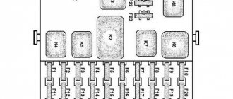
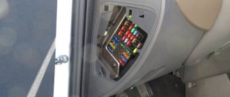
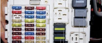
- The fuse has blown. The problem is considered the most common. If your car has a relay that switches the hazard warning lights and turn signals, then this could be the reason. Please note that the part can be mounted either in the main fuse box or separately from it - it all depends on the car model. To find the device, use the diagram.
- The light bulb has burned out. This is another reason why turn signals and emergency lights do not work.
- Short circuit in the wiring.
When a command to turn on is given, the signals may be confused. For example, the driver activates the hazard warning light and the turn lights are activated, or vice versa. If there is a short circuit, the optics may not react at all to the actions of the car owner. To diagnose a breakdown, you need a tester and basic knowledge of the electrical part. - Damage to the switch under the steering wheel or button. To identify a malfunction, it is necessary to check the functionality of these devices.
- Open circuit.
This breakdown is typical for older cars. If the wires are laid in places where there are moving parts, the wiring may become chafed. As a result, the chain breaks.
How to check the operation of lighting devices with your own hands?
If the turn signals or emergency lights do not work, this is not a reason to despair - all diagnostic work can be done with your own hands. First, determine that the light signals really need to be checked. This is done for a number of reasons:
- There are no turn signals, but the lights are on. This problem indicates a failure of the relay, namely its electromagnetic part. As a rule, a malfunction indicates a short circuit of the electromagnet in one of the positions and the impossibility of returning to its original position.
- The turn signals work, but too slowly or in accelerated mode.
With such symptoms, the cause of the malfunction may not be only the relay. As a rule, the problem manifests itself when choosing the wrong light bulbs. When purchasing lighting devices, it is important to check that they correspond to the rating set by the car manufacturer. - There is no response to the power-on command.
In this situation, the turn signals do not work and the indicators on the dashboard do not work. In addition, there are no clicks that should be present when the signals are working. There may be several reasons for the malfunction, and we will talk about them in more detail below.
Connection diagram for hazard warning lights and turns on a VAZ (classic)
The check is carried out as follows:
- Make sure that the indicators and gauges on the vehicle's dashboard are operating normally. If not, check the fuses for integrity.
- If all devices are working properly, press the emergency light button and check the light bulbs in each of the headlights.
Inspect the front and rear lights, as well as the side lights (if the vehicle has them). - If the alarm does not work after issuing the command, check that the relay is working properly and that there is power at the terminals.
To do this, remove the relay from its place, and then connect the signal lamp to the contacts - to the “plus” and the car body (or “minus” of the battery). There is no need to turn the key in the ignition.If the indicator lamp does not light, then the probable causes are a breakdown of the alarm button, a breakdown in the electrical circuit, or a burnt-out fuse insert. In addition, the malfunction may lie in poor contact at the connections.
- If the control light is on, short-circuit the relay terminals using a piece of copper wire. If the remaining elements of the circuit are in good condition, all signals should work. Otherwise, the problem lies in the relay.
- If after the completed manipulations the lamps do not light up, then the cause of the problem is in the button that turns on the alarm. From operating experience it is known that such a malfunction rarely occurs - more often the problem is caused by a short circuit in the circuit. By the way, it is this malfunction that can cause the relay to fail. To avoid repeated costs, first eliminate the short circuit, and then replace the failed part.
Video: Turn signal relay VAZ (classic). Check, diagram, principle of operation
If the video does not show, refresh the page or ” style=”color:#CC3333″>click here
In a situation where the alarm system is working, we can talk about the serviceability of the relay and the safety element. Therefore, attention should be paid to the button itself. First, check the “positive” terminal, as is the case with a relay. To perform the work, the ignition and hazard warning button must be turned on. Next, draw your conclusions:
- If the diagnostics show that there is no “plus”, check the button. Take it out of its place and make sure the switching circuit is working. If there is no power, look for a break in the wiring between the button and the dashboard.
- If the test result confirms the presence of a “plus”, close the terminals at the installation site (the ignition should remain on).
Now activate your turn signals - left or right. If the lights glow normally, change the control button. If there is no power, make sure there is voltage at the alarm relay. If there is no “plus”, the problem, as a rule, lies in the section of the electrical circuit - between the fuse block and the control button.
Connection diagram for turns on a VAZ 2110
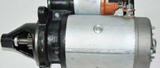
DIY repair
Repairing a failed turn signal relay usually involves replacing the part. Its cost is not so high as to take a radio electronics course and try to repair a failed relay. The turn relay itself is located in the relay and fuse box, usually located under the front panel of the car. In some car models, the turn signal relay is placed in a separate connector.
Replacing the relay is not difficult. To do this, you need to determine its exact location (you can find it in the manual for a specific car model or look up a diagram on the Internet). The broken relay is dismantled, and a new one is installed in the relay unit or in a separate connector. The voltage of the new unit must correspond to the vehicle's electrical power supply (12 or 24 volts).
For those who still prefer to do the repairs themselves, here are some tips. If the contacts of the relay are burnt, you can try to clean them, but this measure is unlikely to last long. You also need to solder broken contacts if there is this type of damage. If there are cracks in the power terminals of the relay, then they also need to be soldered. Capacitors that have lost capacity or are swollen should be replaced with new ones.
Naturally, for such repairs you need to have a soldering iron and know how to use it. Repairing a relay in this case is no different from repairing any radio-electronic part. You will need flux and solder, and when replacing capacitors, you must not forget about the correct polarity.