Why does oil appear in the distributor, what should I do to eliminate it?
- Why does oil appear in the distributor, what should I do to eliminate it?
- Purpose of the distributor and its design
- Why does oil get into the distributor?
- Distributor repair, step-by-step instructions
- Distributor, assembly nuances
- Ignition adjustment, some points
A car engine is a rather complex device, and for its full functioning, the coherence of all parts and mechanisms is necessary. So, for example, one of the important elements of gasoline units is a distributor-distributor or simply a distributor.
Purpose of the distributor and its design
It is no secret that the normal operation of the power plant directly depends on the timely formation of a spark. The distributor is precisely the important element that is responsible for its appearance at the right moment, that is, when the piston has reached TDC. Simply put, without a distributor breaker, most gasoline internal combustion engines will not be able to operate.
If we evaluate the role of the distributor in the ignition operation, it is worth noting that it:
– provokes the appearance of a spark by breaking the breaker contacts (in modern vehicle models a Hall sensor is used for this);
– directs the high voltage generated in the ignition coil to the desired spark plug;
– changes the beginning of the moment of spark formation in accordance with the driving mode and the fuel used (for this, vacuum and centrifugal regulators are installed);
– is responsible for the accumulation and discharge of energy in the reel.
The main components of the device include:
• distributor drive (rotor, which is presented in the form of a splined shaft that engages with the camshaft gear or a special shaft, which depends on the design of the power unit);
• ignition coil with double winding;
Diagram of the EPHH carburetor system 2108, 21081, 21083 Solex
• breaker – contains a jaw clutch, a group of contacts and a centrifugal clutch;
• distributor – presented in the form of a slider attached to the clutch drive shaft, which rotates with it;
• distributor cover (it is from this that high-voltage wires extend to each of the spark plugs).
In addition, integral components of the distributor device (in particular, on VAZ group cars) are a vacuum ignition timing regulator and a capacitor, which is used to collect a certain part of the charge, which protects the contacts from rapid melting due to exposure to high voltage. Based on the type of distributor, an octane corrector can be installed in its lower part, which is connected to the drive roller, which regulates the rotation speed according to a certain type of gasoline, that is, its octane number. In older versions of the device, this indicator is adjusted manually.
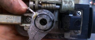
Why does oil get into the distributor?
The most common reasons for oil getting into the distributor of VAZ cars is a clogged hole in the base of the carburetor mechanism (intended for crankcase ventilation) and worn out oil seal. To eliminate these troubles, in the first case it is enough to clean the hole (preferably with the help of service station specialists), and to solve the second problem you will have to replace the problematic oil seal. Every car enthusiast can perform this task independently, but it is still better to turn to specialists.
How to fix starter malfunctions with your own hands
The electrical component of the starter consists of the following structural elements:
- winding;
- brush assembly;
- solenoid relay.
When checking the solenoid relay, skip the starter operation, bypassing its switching. The relay has 3 terminals at once, one of which is the control terminal. The remaining 2 large terminals, located at the input to the battery and at the output of the starter, are closed using a screwdriver or wrench. Closing for a short period of time is enough, the main thing is that the tool you are using does not touch the metal body directly under the hood.
Remember that starting the engine in this way is prohibited, because the main gear of the device does not engage.
Most likely, the contact planes on the inner plane simply burned out, and therefore a dielectric layer of metal oxides formed on top. To burn the contacts, there is no need to make great efforts; just one start of the VAZ-2109 engine is enough.
How to remove the ignition switch on a classic
There are 2 ways to repair the VAZ-2109 solenoid relay:
- Dismantle the device and disassemble it into components, clean the contacts.
- If it is financially possible, it is better to replace the relay completely. Practice shows that if a relay fails, the contacts will have to be cleaned more and more often to restore its operation. If you want the repaired relay to last a long time, give preference to this option for repairing the starter if the device does not spin or click.
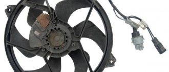
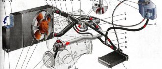
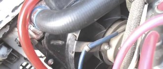
Fan
If the problem lies in the injector or carburetor cooling fan, then you will have to remove it. It is quite possible to repair the unit by replacing the electric motor or impeller.
Diagram with casing, radiator, fan and impeller
To remove the valve, perform the following operations:
- Disconnect the negative terminal from the battery;
- Disconnect the wire terminals. One of them is mounted on the fan casing;
- Take a wrench and unscrew a couple of connecting bolts. They fix the vent casing on the left tank;
- Next, unscrew another lower nut holding the device casing;
- Now you will need a socket extension to unscrew the right nut on top that secures the vent housing to the radiator;
- All that remains is to unscrew the fan pressure plate. To do this, remove the pair of left nuts;
- Remove the pressure plate by hand;
- Now remove the fan along with the casing.
You have removed the unit. Now you have a choice - change the entire unit, or try to repair it by replacing the electric motor or impeller if they are damaged.
Replacing the electric motor
- Disconnect the fan motor wire that is held in place by a clamp on the casing.
- The electric motor is held on the casing by three nuts. They all need to be unscrewed.
- Remove the electric motor from the fan housing.
- Be sure to check the condition of the rubber bushings of the electric motor, which will remain on the casing. If cracks or signs of deformation are detected, they must be replaced.
- Check the electric motor for functionality. If it fails, you can purchase a new one and insert it into the old casing.
Electric motor
It is not uncommon that the performance of a radiator fan is impaired due to a deformed impeller. By replacing it, you can restore functionality to the device.
Replacing the impeller
To change the impeller, follow the instructions:
- Pry up the lock washer using a flathead screwdriver. It is located directly in the center of the impeller;
- Lift the washer and remove it;
- In some cases, the impeller is secured to the fan motor with a nut. Therefore, if you have one, unscrew the mount;
- Remove the impeller and assess its condition. If it is worn out or deformed, replace it with a new one;
- Many people, instead of a standard 4-blade impeller, install a more advanced 8-blade impeller.
Changing the impeller
During reassembly, make sure that the motor pin fits into the longitudinal hole on the impeller, as shown in the figure below.
Direct the pin into the longitudinal hole
Where is the fan relay VAZ-21099 injector
Quite often a problem arises with the Ninety-Nine when the engine fan does not turn on and the coolant begins to boil. If such a malfunction occurs, first of all they check the functionality of the fan itself by applying voltage directly to it from the battery, but there may be other problems.
In order to check the entire circuit, it is important to find where the VAZ-21099 injector fan relay is located, since it is precisely this that is responsible for turning on the airflow. We find this part in the front of the car, on the passenger side, it is installed under the glove compartment, at the passenger’s feet
The required relay in the picture is indicated by an orange circle, and here you will also find a fuse that blows when the cooling fan is short-circuited.
Why doesn't the cooling fan work on the VAZ 21099?
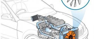
The operation of the cooling fan is very important, especially in summer when the temperature is high. In the hot season, the likelihood of engine overheating greatly increases, so the correct functioning of the cooling system by means of a cold air flow that is supplied to the radiator is very important. If the car's cooling system, and in particular the fan, fails, then the liquid in the system inevitably boils, which can lead to a complex breakdown.
When the cooling fan does not turn on at low vehicle speeds, the first thought of many car enthusiasts is that the problem is in the thermostat. As a rule, in this case, the fluid in the radiator stops circulating. But in reality there can be many more problems with the cooling system.
Most often, problems with a non-working fan occur in cars with high mileage, and due to the similarity of the design of the cooling system, they can be applied to any model of the Lada family.
First of all, you should pay attention to the breakdown of the thermostat. It is very easy to check its functionality. To do this, you need to touch the bottom of the radiator; if it is cold, but the water is boiling, then most likely the fan is fixed, and the problem lies in the thermostat. On the contrary, if the radiator is hot, the thermostat is corrected and the reason for the lack of cooling lies in the fan.
Wiring diagram for the ignition switch on the VAZ-2108, 2109 and 21099
Pinout of the VAZ-2109 ignition switch with unloading relay:
- comes +12V in position I, II, III (parking)
- comes +12V in position I, II, III (parking)
- comes +12V in position III (parking)
- position I, +12V goes out after turning on the ignition (contact 15/2), disappears at start (II);
- position I, +12V goes to the starter (pin 50);
- position I, +12V goes away after turning on the ignition (pin 15), does not disappear when starting II;
- +12V comes from the battery (pin 30);
- comes +12V constantly.
Wiring diagram for the ignition switch on the VAZ-2108, 2109 and 21099 of the new model, without a relay.
Pinout of the new VAZ-2109 ignition switch:
Design features and self-repair of the ignition switch of the VAZ 2101
- comes +12V constantly
- comes +12V constantly
- +12V arrives after turning on the ignition (pin 15), does not disappear when starting II;
- +12V arrives after turning on the ignition (contact 15/2), disappears at start (II);
- position I, +12V goes to the starter (pin 50);
- +12V arrives after turning on the ignition (pin 15), does not disappear when starting II;
- +12V comes from the battery (pin 30);
- comes +12V constantly.
Photo 1, pinout of the new VAZ 2109 ignition switch
Photo 2, pinout of the new VAZ 2109 ignition switch
What is
First, let's look at the structure of the castle. Let's find out what it looks like, what it consists of, what its operating principle is, and so on:
As mentioned, the ignition switch is a very important element of the VAZ 2109 car, because almost all available equipment is connected to it.
VAZ 2109 ignition switch malfunction
Scheme
Below is a typical diagram of the ignition switch on the “nine”.
| In key position “0” | The VAZ 2109 is de-energized, and there is power only in the wires that go directly to the battery |
| In key position “1” | The following car components are working: external lighting, headlights, instrument lighting, interior light, all control devices, wipers, heated windows, etc. |
| In position “2” | The starter turns on and all position “1” circuits work |
| In position “3” | All circuits including brake light |
Sensor
Don't rush to change the fan right away. Often the problem was a sensor, relay, fuses, or simply broken wiring. First of all, we will check the sensor and also tell you about the features of replacing it.
Signs of a faulty sensor may include failure to turn on when the coolant temperature is high or turning on when the engine is cold.
The fan switch sensor is located at the bottom of the radiator. A couple of wires come off it.
Searched device
Accurate check
In order not to rush to conclusions, experts first advise checking the sensor for functionality.
- If the fan does not want to turn on according to the standard circuit, try shorting the wires that go to the sensor. If the fan is running and the sensor is hot, the problem lies there. If the radiator is hot during testing, the sensor housing may be warm. This suggests that you should check the condition of the thermostat and the coolant level in the tank. You may need to change and top up accordingly.
- If, after closing the wires, the fan does not turn on, the sound of the relay being activated is not observed, check the condition of the relay and fuse. It is number 4 in the mounting block.
- By shorting the wires, the fan did not start, but the relay worked. Here you should check fuse number 8.
- If the fan starts randomly on a cold engine, it does not turn off for a long time, try disconnecting one wire from the sensor. If the fan stops, the sensor contacts are stuck. If the fan continues to turn, sticking has occurred on the contacts of the control relay.
Having discovered that the regulator has failed, there is nothing left to do but change the radiator fan activation sensor.
Replacing the sensor
Changing the sensor is quite simple:
- Turn off the ignition;
- Drain the coolant from the expansion tank;
- Disconnect a pair of wires from the sensor terminal block;
- Using a 30 mm wrench, unscrew the regulator from its seat. You shouldn’t apply a lot of force; you risk breaking the seat;
- Following the reverse sequence, install the new sensor.
Disabling the sensor
You can change the sensor without draining the coolant. To do this, you need to quickly unscrew the old regulator and screw in a new one in its place. A small part of the coolant will spill out, but you won’t have to drain it for a long time and then pour it back in.
Pinout of lock VAZ-2108, VAZ-2109, VAZ-21099
Pinout according to the old type
Pinout of the VAZ-2109 ignition switch with unloading relay:
- comes +12V in position I, II, III (parking)
- comes +12V in position III (parking)
- position I, +12V goes out after turning on the ignition (contact 15/2), disappears at start (II);
- position I, +12V goes away after turning on the ignition (pin 15), does not disappear when starting II;
- comes +12V constantly.
New pinout type
Pinout of the new VAZ-2109 ignition switch:
- comes +12V constantly
- comes +12V constantly
- +12V arrives after turning on the ignition (contact 15/2), disappears at start (II);
- position I,
- +12V arrives after turning on the ignition (pin 15), does not disappear when starting II;
- +12V comes from the battery (pin 30);
- comes +12V constantly.
Typical faults
VAZ 2109 ignition switch
The lock belongs to the car's ignition system. Let us note right away that if problems are observed, you can fix them yourself, because, as a rule, the “nine” is equipped with an outdated ignition system that does not require diagnostics and repair at a service station.
How to make sure there is a problem
Below is a tip on how to make sure that the ignition switch is really not working:
- We insert the ignition key and turn it to a certain position. A short circuit in the circuit must necessarily occur. We look at the diagram: if the key is in position “1”, is the external lighting or control devices working;
- It is recommended to check at all positions of the lock. If deviations from the norm are observed, there is a problem with the lock;
- You can also check the functionality of the ignition switch in the following way: turn the steering wheel, which should not be blocked. The lock on a working steering wheel should only work when the key is turned a second time from position “1” to position “2”;
VAZ 2109 ignition switch malfunction
You can reliably check whether the lock works like this: take an ordinary portable lamp and connect one end to ground, the other to the lock. We turn on the ignition - if the light is on normally, then the lock is in order. If the light glows dimly or does not light at all, the lock is faulty.
Malfunctions of the ignition switch in a VAZ 2109
Common faults
Among them, the following are in first place:
The lock is jammed. This is even observed in the “nines” when a new lock is installed. The reason is a manufacturing defect or what is given below.
- The lock may wear out over time and this will cause it to perform poorly;
- The ignition switch easily becomes unusable in the event of an unsuccessful attempt to steal a car, as well as any careless handling.
Power-up modes used
At each of the turns, the connection of certain devices is provided. There are markings in a circle in front of the socket indicating the position to which a certain mode corresponds.
Null
To activate this mode, just insert the key into the “secret”. In this case, devices that are directly connected to the battery remain active.
Additional consumers will be put into operation after the larva is rotated at a certain angle. Voltage is supplied to pins 30/1 and 30.
The first is “ignition”
In the first position, the driver can turn on the front lighting, such as the low and high headlights. The tidy and interior light up responsively. The connection diagram for the VAZ-2109 ignition switch is activated during this turn, releasing current to the 30–INT pair.
When there is a connection between terminals 30/1 and 15/1, the rear lights, reversing lights, turn signals are operational, and the generator excitation winding is energized. The XX solenoid valve also receives power.
In this position, contacts 30/1 and 15/2 are closed, which ensures the operation of, in addition to the head light optics, the functioning of the fog lights, the rear window wiper and its heating. The headlight cleaners, heater fan and engine cooling system propeller are connected to this contact.
The second is the “starter”
By moving the key to the current position, the driver does not block the connection of electrical consumers that were started in the previous “ignition” position. This fully applies to both the closed contacts of the pair 30/1 - 15/1, and to the pair 30 - INT.
The main change that the VAZ-2109 ignition switch connection diagram provides in such a situation is the activation of a pair of contacts 30–50. This allows the starter to start.
Third – “parking”
At this angle of rotation, consumers started in the “ignition” position and closed contacts 30 – INT remain activated. A closed pair 30/1 - P is also added. It is responsible for the parking lighting.
Name of modes, position of the lock and power circuit.
| Key position in the lock | Live pin numbers | Circuits that are included |
| 0 - disabled | 30 and 30/1 | The car is de-energized, power is provided only in circuits connected directly to the battery |
| "I" - ignition | 30 - INT | At the current position of the key, the external lighting, high and low beam headlights, instrument lighting and lighting in the car interior work. |
| 30/1 — 15/1 | All control devices, reversing light, windshield wiper, generator excitation winding, direction indicators, idle speed solenoid valve control unit must work. | |
| 30/1 — 15/2 | In this position, the low and high beam headlights, rear front fog lights, rear window cleaner and heating, washer, heater fan, engine cooling system fan, and headlight cleaners operate. | |
| "II" - starter | 30 - INT | The same circuits operate as in the ignition position. |
| 30/1 — 15/1 | The same circuits operate as in the ignition position. | |
| 30 — 50 | The starter turns on | |
| "III" - parking | 30 - INT | The same circuits operate as in the ignition position. |
| 30/1 - R | Parking lighting |
Where is the speed sensor located?
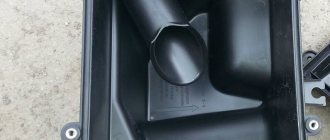
The speed sensor (DS) on front-wheel drive VAZ cars reads pulses depending on wheel speed and transmits the data to the electronic control unit (ECU). When braking the engine, the fuel supply is turned off with the help of the diesel engine and the computer, thus achieving more economical operation of the internal combustion engine. If the sensor is faulty, an error code is recorded, gasoline consumption increases slightly, and idle speed decreases, especially during heavy braking. It is difficult to immediately detect where the speed sensor is located, since it is hidden under the air filter housing (AFC).
We find the part we need as follows:
- open the hood of the car;
- Using a 10mm wrench, unscrew the two KVF fastening bolts;
- loosen the clamp of the air “corrugation”, disconnect the “chip” with the wires;
- we take out the KVF, now the sensor has already appeared in the field of view, it is located on the gearbox (gearbox) housing, wires are connected to it, connected using a connector.
The DS can be easily unscrewed by hand, and the plug with wires can be pulled out even after the sensor has been unscrewed (but carefully so as not to damage the wiring during rotation).
Where is the ignition relay located in a VAZ-2114 car?
If a car owner independently monitors the technical serviceability of his four-wheeled friend, then he must feel his car and know exactly where this or that element is located in order to quickly replace a component that has become unusable with a new one.
For example, the driver may notice the following:
- the furnace fan will start to work intermittently;
- The windshield wiper and glass heating either turn on normally or refuse to work;
- the engine started to have trouble starting.
You should not immediately look for a breakdown in the starter or car module, because most often such a breakdown is caused by a starter relay that has become unusable. Experts do not recommend repairing such an element, since a failed element, even if it is thoroughly repaired, will very soon show signs of malfunction again, so the entire replacement operation will have to be repeated again. Replacing the so-called relay yourself is quite simple, but before doing this you should know exactly where the ignition relay is located on the VAZ-2114. We will deal with this issue, as well as with independent replacement of the “relay”, further in this article.
How to check the serviceability/failure of the ignition switch of the “nine”?
The ignition switch, like any other element of the car, can fail. In such a situation, it is necessary to either repair the ignition switch or, in case of a serious malfunction, simply replace this element with a new one. However, in the latter case, before carrying out this very replacement, you should make sure that the ignition switch is actually faulty. How to do it?
The ignition key must be inserted into the ignition switch and this key must be installed in a certain position. During such actions, the circuit must be closed, which is used to judge the functionality of the lock. For example, when the ignition key is turned to the third position, the security system should begin to operate, and when the key is turned to the zero position, this system should turn off. Any deviations here will indicate actual problems with the ignition.
Another way to check the lock's functionality is to turn the steering wheel. It shouldn't be blocked. The lock should only operate when the ignition key is turned a second time from the first position to the second. And the key, as you know, can only be turned to the second position from the zero position.
Variety of locks for VAZ 2109
Having abandoned the left-hand drive position as in the “classics”, the designers took care of a comfortable right-hand place for using the key in their first front-wheel drive cars. This added ergonomics to the cabin. To perform its function, the main element used to start the car is equipped with two components:
The first block is responsible for fixing the steering wheel while the key is removed. The second block contains the pinout of the VAZ-2109 ignition switch, which is entrusted with the mission of supplying voltage to consumer electrical appliances.
The developers have provided for the presence of certain electrical devices in the ninth Lada model, which are capable of operating regardless of the state of the ignition unit. These include:
- car flashing emergency lights;
- “stops” of rear lights;
- dimensional optics;
- interior lighting;
- instrument panel light bulbs.
It must be taken into account that the VAZ-2109 ignition switch circuit is adjusted to its direct variety. Two types of locks can be installed in the “nines”:
- late model, which has three positions, does not use a relay and is activated with a short key;
- an early example that has four detent positions, a built-in relay and a long key.
Typically, drivers can easily visually determine the type of system installed. You can navigate by the working length of the key.
Check and replacement
If the car shows signs of malfunction, there are signs of breakdown of elements of the ignition system, do not rush to immediately blame the starter or module for everything. Often the culprit may be an element that is insignificant in size and cost - the relay.
Dismantling works
To check the relay you need:
- Arm yourself with an ohmmeter or a multimeter more suitable for a motorist, which has all the necessary modes;
- Check resistance indicators;
- We check the holding coil by connecting one terminal of the tester to the relay connection terminal, and the second to ground, that is, the housing;
- Next, the pull-in winding is checked. Here the terminals are connected to the starter motor field winding connection bolt and the control wire connection bolt;
- If there is no resistance, there is only one output - failure.
Checking with a multimeter
Repairing the ignition switch does not make any sense. The element can only be replaced. Plus, it costs pennies.
To replace, you will need to perform a few simple steps. You don't have to be a car repairman here.
- Disconnect the battery by removing the negative terminal.
- Using a slotted screwdriver, unscrew the four screws on the steering column housing. This will allow you to easily remove the element.
- Using a Phillips screwdriver, unscrew another screw that holds the bottom of the casing in place.
- Remove the steering column protective cover.
- At the bottom there is a block of the harness with wires where the ignition relay is connected.
- To replace the relay, you simply need to disconnect the device from the block and install a new element in its place.
- Check the performance of the car with a new transmission.
Useful tips.
Emergency relay for contactless ignition of VAZ. As you can see, there is nothing difficult about checking and replacing the device. It does not fail very often, but it is worth monitoring the condition of the ignition relay.
Loading …
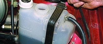
Checking and replacing the temperature sensor
On a VAZ-2109, the cause of untimely operation or complete failure of the fan is often the coolant temperature sensor. Therefore, it needs to be checked secondarily. The sensor is located at the bottom of the radiator, two wires come from it. Before unscrewing it, you need to accurately check the operation of the cooling system:
- Connect the ends of the wires leading to the sensor together. If after this the fan starts working and the sensor gets hot, then this controller needs to be changed. When testing on a hot radiator, you may find that the sensor body is also warm. In this case, check the thermostat.
- If the fan does not work even after shorting the wires, then the problem may lie in the relay or fuse. The relay should be checked if the sound of its operation is not heard. Depending on the type of car, it may be located in the mounting block (for models with carburetors) or in the passenger compartment under the driver’s storage compartment (for injection cars). The easiest way to check this device is to install a similar device in its place. If after replacing the relay the fan starts working, you don’t have to carry out further testing.
- Sometimes the device does not work, but the sound of the relay operating is present. In this case, check fuse F-8.
If you do not find any faults in other systems, then you need to replace the temperature sensor in the cooling system. This is done according to the instructions:
- Turn off the ignition, remove the terminal from the battery and drain the fluid from the expansion tank and the generator. To do this, you need to remove special plugs.
- Then disconnect the sensor from the terminal block.
- Using a spanner wrench, unscrew the sensor from its place without applying excessive force.
Install a new sensor and reassemble. Some car enthusiasts prefer not to drain the antifreeze from the system, but simply act quickly. In this case, after the sensor leaves the seat, a certain amount of coolant will leave the system, so it will need to be topped up.
Decoding fuses and relays of block 2114-3722010-18
VAZ-2114, 2115, 2113 cars of the first models with a carburetor have certain differences in the fuse module.
Old style block fuse and relay diagram
Table 2. Decoding of fuses and relays of block 2114-3722010-18
| № | Current, A | Explanation of fuses |
| F9 | 7,5 | Right rear fog lamp |
| F8 | 7,5 | Left rear fog lamp |
| F1 | 10 | Front headlight cleaners at the moment of switching on, wiper contacts, headlight washer switch valve, headlight wiper switch relay contacts |
| F7 | 30 | Front headlight wipers during operation, winding of the relay for turning on the wipers, fuse for the interior heater, windshield washer, gearbox and timing controller for the rear window wiper, valves for turning on the front and rear washer, relay (winding) for turning on the engine cooling system, relay for turning on the rear window heating, glove box lighting, rear window heating control lamp |
| F16 | 15 | Turn signal indicators and activation of hazard warning lights in turn mode, indicator control lamp, reversing lights, gearbox and relay for activation of windshield washers, generator winding (at startup), control lamps for brake fluid, oil pressure, carburetor flap, hand brake. "STOP" display lamp, voltmeter and coolant temperature indicator |
| F3 | 10 | Interior lighting and rear brake light |
| F6 | 30 | Power windows, power windows on/off relay |
| F10 | 7,5 | License plate lights, engine compartment lamp, warning light on the dashboard (exterior lighting), instrument panel lights, cigarette lighter light, heating lever lights |
| F5 | 20 | Relay for turning on the cooling system fan (electric motor), sound signal. |
| F10 | 7,5 | Left front marker light Left rear marker light |
| F11 | 7,5 | Right front headlight, right rear |
| F2 | 10 | Hazard warning lamp, turn signals and hazard warning relay. |
| F4 | 20 | Rear heated glass, heating on, portable socket, cigarette lighter in the cabin |
| F15 | 7,5 | Front right high beam |
| F14 | 7,5 | Front left high beam Light switch |
| F13 | 7,5 | Left low beam |
| F12 | 7,5 | Right low beam |
| № | Relay circuit | |
| K1 | Headlight washers | |
| K2 | Hazard and turn signals | |
| K3 | Windshield wipers | |
| K4 | Monitoring the health of lamps | |
| K5 | Windows | |
| K6 | Sound signal | |
| K7 | Heated rear window | |
| K8 | High beam headlights | |
| K9 | Low beam headlights |
Checking status
Before changing the relay, make sure that the problem with starting the engine is related to this component.
To do this, consider two situations that indicate its malfunction.
Situation
Your actions
The relay makes clicks, but the armature does not spin
If there are clicks from the relay, check the condition of the armature. To do this, the terminals of the retractor relay are bridged with a large screwdriver or a piece of welding cable to the terminals at the ends. Taking a thin wire or a screwdriver can easily burn the terminals. When the armature is working, after closing the terminals, the armature will spin, which can be determined by the sound. Consequently, the solenoid relay itself has failed and requires repair.
The relay is completely silent
Even if there is silence after closing the terminals, the problem should be looked for in the starter. The relay no longer plays any role here.
Having discovered that the relay has served its purpose, it must be replaced or repaired, if possible.
The VAZ clicks when starting, replacing the starter solenoid relay. We disassemble the VAZ 08 09 099 starter retractor, causes of malfunction, part 1. Do-it-yourself repair of the starter solenoid relay.
Examination
On VAZ 2109 engines, the operating temperature is 90 degrees.
If the indicator needle crosses the 100 degree mark, the car should be stopped immediately, the engine should be turned off and the power unit should cool down. Without doing this, you risk major, expensive engine repairs.
The motor can overheat for various reasons:
- The thermostat has failed;
- The radiator is clogged;
- The radiator fan has failed;
- The fan switch sensor is broken;
- The coolant level in the system has dropped;
- The pump has failed;
- The integrity of the wiring in the fan circuit has been compromised.
All these reasons can and should be checked before purchasing new parts.
Here is an example of checking a fan and sensor.
| Object to be checked | Method |
| Fan | Take one wire about a meter long. Preferably with two crocodiles at the ends. The mass goes to the fan. Your task is to supply voltage directly from the battery to the fan. Apply 12 volts to the second contact of the fan. If he's spinning, he's fine. If not, you'll have to change it |
| Fan sensor | Turning on the ignition, close the sensor contacts with a screwdriver. Normally, when it is closed, the fan should start spinning, and if it is open, it should stop. Please note that different types of sensors have a certain response temperature - from 87 to 90 degrees or more |
Sensor
Types of ignition switches for VAZ 2109.
The ignition switch, as already mentioned, is a very important element in any car. Almost all equipment in a car operates through the ignition switch. What is the exception? Regardless of the ignition switch, only the rear license plate illumination, side lights, brake lights, hazard warning lights, instrument panel illumination and interior lighting function in the Nine.
At the same time, the ignition switch itself on VAZ 2109 cars can be different: a new model - with three positions, a short key and without an ignition relay, or an old model - with four positions, a long key and a relay.
What does the VAZ 2109 ignition relay consist of?
When an electric current passes through the coil, an electromagnetic field is created there, and under its action the armature moves inside the core. When the power is turned off, the field disappears and the armature moves freely in the core. The VAZ 2109 ignition relay consists of an electromagnet, which is wound from an armature, a return spring, contacts and two windings.
The electromagnet consists of two coils: holding and retracting. The retractor is connected to the electric motor contact and the control terminal, and the retainer is connected to the relay body and the control terminal. When voltage is applied to the relay control contact, an electric current flows through the coils, creating an electromagnetic field there, and under its action the armature moves and compresses the return spring.
The structure of a car ignition switch
- Locking rod
- Frame
- Roller
- Contact disc
- Contact sleeve
- Block
- Protrusion of the contact part.
The lock mechanism is connected to many wires. They continue from the battery, connecting all the electrical devices of the car into a single chain. When you turn the ignition key, the electrical circuit is closed from the “-” terminal of the battery to the ignition coil. As a result, the current passes through the wires to the ignition switch, through its contacts it is directed to the induction coil, after which it returns back to the “+” terminal. As electricity passes through the coil, it generates high voltage, which it transmits to the spark plug. Therefore, the key closes the contacts of the ignition circuit, thereby starting the car engine.
How does the VAZ 2109 ignition relay work?
The armature is also moved by the bendix, and later by the rod, which closes the contacts that the battery closes with the starter motor. When the contacts close to the terminal of the retracting winding, which goes to the motor terminal, a plus is applied and the current stops passing through it - the magnetic field disappears, but the armature still remains in the retracted state under the influence of the magnetic field of the holding winding.
The armature returns to its original position after starting the engine and turning off the power by the action of the return spring, opening the contacts and disengaging the bendix. The contacts of the pull-in relay are bolts that are fixed in a textolite cover and rectangular or round plates that close the bolts when the armature moves.
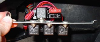
Mounting block VAZ 2109
732 Google+
The VAZ 2109 mounting block is designed to combine wiring harnesses, as well as to accommodate relays and fuses. The first models used a mounting block type 17.3722. It consists of a housing consisting of two parts and a printed circuit board on which leads are soldered for connection to the wiring harness blocks, installation of relays and fuses. Below is a schematic diagram of a VAZ 2109 mounting block type 17.3722.
The latest models use a VAZ 2109 mounting block type 2114-3722010-60. This unit uses flat blade-type fuses. The contact connection of such fuses is more reliable since they have a large contact area.
The replaceability of electrical wiring harness plug connectors is identical to block 17.3722. The fuse designations and protected circuits are slightly different. The VAZ 2109 mounting block diagram is shown below
On cars with an injection engine, mounting blocks similar to 2114-3722010-60 are used, but they have a different connection for the radiator cooling fan. Below is the location of the mounting block plugs.
Below are the characteristics of the fuses and the protected circuits.* Fuse numbers with the letter F refer to the fuses of the mounting block 2114-3&22010-60
| Fuse no.' | Protected Circuits |
| 1 (8 A) F9 (7.5 A) | Right fog lamp |
| 2 (8 A) F8 (7.5 A) | Left fog lamp |
| 3 (8 A) F1 (10 A) | Headlight cleaners (at the moment of switching on). Relay for turning on headlight cleaners (contacts). Headlight washer activation valve |
| 4 (16 A) F7 (30 A) | Headlight cleaners (in operating mode). Relay for turning on headlight cleaners (winding). Heater fan motor. Window washer motor. Rear window wiper motor. Rear window washer timing relay. Valves for turning on the windshield and rear windows. Relay (winding) for turning on the electric fan of the engine cooling system. Relay (coil) for turning on the heated rear window. Control 'Heated rear window lamp. Glove box lighting lamp |
| 5 (8 A) F16 (15 A) | Direction indicators and relay-interrupter for direction indicators and hazard warning lights (in turn indication mode). Turn signal indicator lamp. Rear lights (reversing lamps). Gearmotor and windshield wiper activation relay. Generator excitation winding (when starting the engine). Brake fluid level warning lamp. Oil pressure warning lamp. Carburetor air damper warning lamp. Parking brake warning lamp. Light display lamp "STOR". Coolant temperature gauge. Fuel level indicator with reserve warning lamp. Voltmeter |
| 6 (8 A) FZ (10 A) | Rear lights (brake lamps). Interior lighting |
| 6(8 A) F6 (30 A) | Power windows for front doors. Power window relay |
| 7 (8 A) F10 (7.5 A) | License plate lights. Engine compartment lamp. Instrument lighting lamps. Indicator lamp for external lighting. Heater lever illumination display. Cigarette lighter lamp |
| 8 (16 A) F5 (20 A) | The electric motor of the engine cooling system fan and its activation relay (contacts). Sound signal and relay for its activation |
| 9 (8 A) F10 (7.5 A) | Left headlight (side light). Left rear light (side light) |
| 10 (8 A) F11 (7.5 A) | Right headlight (side light). Right rear light (side light) |
| 11 (8 A) F2 (10 A) | Direction indicators and hazard warning relay-breaker (in hazard warning mode). Hazard warning lamp |
| 12 (16 A) F4 (20 A) | Rear window heating element. Relay (contacts) for turning on the heated rear window. Plug socket for portable lamp. Cigarette lighter" |
| 13 (8 A) F15 (7.5 A) | Right headlight (high beam) |
| 14 (8 A) F14 (7.5 A) | Left headlight (high beam). Indicator lamp for high beam headlights |
| 15 (8 A) F13 (7.5 A) | Left headlight (low beam) |
| 16 (8 A) F12 (7.5 A) | Right headlight (low beam) |
admin 06/10/2011 “If you notice an error in the text, please highlight this place with the mouse and press CTRL+ENTER” “If the article was useful to you, share the link to it on social networks”
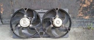
Why the fan does not work - VAZ 2109
Two fans are installed on the VAZ-2109 car . The first, more powerful, is installed in the engine cooling in order to increase air flow through the radiator core. The second fan is installed in front of the heater radiator (“stove”) , its task is to pump heated or unheated air inside the car. Both fans are driven by DC motors.
The fan, which is installed in the hole in the casing covering the radiator core in the electrical circuit for its connection, has a sensor for automatically turning on the electric motor. This sensor is screwed into a threaded hole located in the right radiator tank, since there will be the highest coolant temperature after the thermostat is activated. The fan starts working without driver intervention. The sensor should be triggered when the operating temperature of the antifreeze exceeds 90-95 degrees and send a signal to the electric motor switching relay located in the mounting block. The electrical circuit for switching on the electric motor is protected by fuse No. 4 and No. 8 on mounting blocks of type 17. 3722.
If your VAZ-2109 car is equipped with a mounting block of type 2114-3722010-60, then the fan electric motor is switched on directly from the switch-on sensor, without the participation of a relay. It's just not in the mounting block at all. The electrical circuit is protected by a fuse designated No. 5. In the event of any malfunction in these electrical circuits, the fan will not turn on. The driver will determine this by reading the coolant temperature gauge. The arrow of this indicator will go to the red zone of the scale. In this case, it is necessary to reduce the load on the engine to idle speed, turn on the interior heater fan and open the tap to supply coolant to the heater radiator, start coasting until it comes to a complete stop, to eliminate the causes of the malfunction.
It is necessary to start looking for the cause of malfunctions from motor activation sensor . To do this, open the hood and disconnect the terminal from the sensor. To further check the sensor, you will need a piece of wire, with which you need to short-circuit the two wires suitable for the terminal. Wrap the jumper with electrical tape so that it does not touch the ground of the car. Turn on the ignition, and if everything else is correct, the fan will start working. Moreover, in this case it will work continuously as long as the ignition is on.
If the fan on the VAZ 2109 does not work, then open the cover of the mounting block and check the serviceability of fuses No. 5 on block 2114-3722010-60 and No. 4, No. 8 on block 17. 3722. Look for the fuse number marking on the top of the cover. After making sure that the fuses are in good condition and provided that the fan still does not work, you need to check its electric motor.
To do this, you will need two insulated wires to connect the fan motor terminals directly to the battery. If the fan starts working, make sure that the air flow goes under the hood of the car, and not vice versa. If the connection is incorrect, change the polarity of the wires connected to the battery. When troubleshooting, you can thus get to the repair site, and you can turn off the fan motor only by disconnecting the wires from the battery. In this case, the reason that the fan did not turn on would be either a faulty relay or a faulty wiring.
In order for the driver not to be left alone with such malfunctions, he needs to have in the trunk of his car a coil of car wires three meters long and a supply of fuses , which are located in the mounting block.