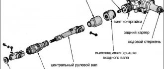
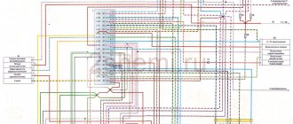
↑ Diagram of the carburetor electro-pneumatic valve control system
1 - microswitch in the carburetor;
2 - pneumatic valve; 3 — mounting block; 4 - ignition relay; 5 — ignition switch; 6 — pneumatic valve control unit; 7 - ignition coil; A - to terminal “30” of the generator; B - order of conditional numbering of plugs in the control unit. A working control unit 25.3761 should turn off pneumatic valve 2 when the engine crankshaft speed exceeds 1600 min-1 and turn it on again when the speed drops to 1200 min-1.
Before checking the operation of the unit, you must make sure that the vehicle wiring harness is connected correctly to the control unit (see view “B” of the control unit connector).
The functionality of the control unit is checked using a tachometer and a voltmeter (with a measurement range of 0–15 V) in the following order:
- disconnect the wires from the microswitch installed on the carburetor;
- connect 1 voltmeter to the control unit using a special adapter connector 2;
- start the engine and, gradually increasing the speed, monitor the voltmeter readings: after starting the engine, the voltmeter should show a voltage of at least 10 V, and at the moment the pneumatic valve is turned off, an abrupt decrease in voltage to a value of no more than 1.5 V;
- after turning off the pneumatic valve, gradually reduce the rotation speed until the pneumatic valve turns on: the voltmeter should show a sudden increase in voltage to at least 10 V.
Diagnosis of idle speed faults
In the carburetor of a VAZ 2107 car, the pneumatic valve is controlled by an electromagnet - solenoid. When current is applied, the valve opens and the mixture is supplied to the cylinders through a special channel, which ensures stable engine operation at idle. The electro-pneumatic valve is quite reliable, the main reasons when it can fail are:
- Violation of the control circuit.
- Clogged air-fuel channel.
- The spring that closes the pneumatic valve after the ignition is turned off has weakened.
All these malfunctions can be diagnosed by external characteristic signs. The engine continues to run after the ignition is turned off (glow ignition), this indicates that the electro-pneumatic valve has failed. This usually happens if the valve does not close completely. There may be various reasons for this, a blockage in the passage hole, a weakened spring.
↑ Checking the functionality of the control unit
The operation of the control unit is checked using an adapter connector with a voltmeter in the following order:
- disconnect the wire from the carburetor limit switch and connect the tip of this wire to ground;
- connect a voltmeter to the control unit using an adapter connector;
- start the engine and, gradually increasing the speed, monitor the voltmeter readings: after starting the engine, the voltmeter should show a voltage of at least 10 V, and at the moment the valve is turned off, an abrupt decrease in voltage to a value of no more than 0.5 V;
- after turning off the valve, gradually reduce the rotation speed until the valve turns on: the voltmeter should show a sudden increase in voltage to at least 10 V;
- set the crankshaft speed within 2200–2300 min-1, disconnect the tip of the wire going to the carburetor limit switch from ground, and then reconnect it to ground. When the wire is disconnected from ground, the valve should turn on, and when connected to ground, it should turn off.
It is possible to check the unit without a voltmeter by the characteristic knock of the valve when turning it off and on.
| Terminal | Address |
| 1 | To terminal "K" of the ignition coil |
| 2 | Weight |
| 3 | — |
| 4 | +12 V from fuse “10” |
| 5 | Carburetor limit switch |
| 6 | Carburetor solenoid valve |
| 7 | — |
EPHH carburetors Ozone 2105, 2107
Carburetors Ozone 2105-1107010 (VAZ 2101, 21011, 2105 with 1.3 l engines), Ozone 2107-1107010 (VAZ 2107, 2104 with 1.45 and 1.6 engines) are equipped with a forced idle economizer system (EFI). It allows you to block the supply of the fuel mixture through the carburetor idle system at forced idle (FID). Let's consider the features of its device and principle of operation.
Purpose of EPHH Ozone carburetors
The forced idle economizer system of carburetors 2105, 2107 Ozone is designed to forcibly stop the supply of fuel to the engine through the carburetor idle system in forced idle mode (when braking the engine with the gear engaged and the gas pedal released). This is necessary to achieve fuel efficiency and improve combustion processes in the cylinders, as well as to prevent engine operation after the ignition is turned off (“dieseling”, glow ignition).
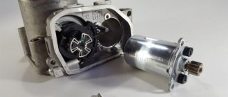
Location by car
An economizer with a needle is installed instead of a screw for adjusting the “amount” of the carburetor fuel mixture. In addition to it, an EPHH microswitch is installed right there on the carburetor, on a special bracket, on the throttle valve block. On the left engine splash guard there is a control unit for the EPH system, on the right there is an electro-pneumatic valve from which there are tubes for supplying vacuum to the fitting on the intake manifold and the fitting on the economizer in the carburetor.
EPCH Ozone device
EPH system of carburetor 2105, 2107 Ozone consists of several elements.
Economizer
It consists of a housing, a shut-off needle that blocks the fuel outlet from the idle system, connected to the diaphragm needle, and an adjusting screw for the “amount” of the fuel mixture.
Microswitch
It sends a signal to the control unit whether the throttle valve of the first carburetor chamber is closed or open. It is turned on or off by moving the lever on the throttle axis of the first chamber. There is a groove in the lever that provides some free play, within which moving the pedal does not cause the throttle to open. Therefore, the driver, pressing the gas pedal, first closes the contacts of the microswitch (sending a signal to the control unit to start opening the throttle), and then moves the throttle. Read more: “Microswitch EPHH carburetor Ozone.”
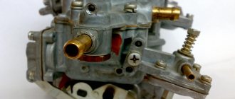
Electropneumatic valve
Vacuum from the engine intake manifold passes through it into the economizer housing. After turning on the ignition, the electro-pneumatic valve is energized and allows vacuum from the intake manifold to enter the economizer housing. At the IAC, the control unit de-energizes it and thus closes the supply of vacuum to the economizer, the needle of which closes the outlet of the IAC. The central fitting of the pneumatic valve is the outlet to the intake manifold, the side one is to the carburetor economizer.
Control block
Receives a signal from the ignition coil about the crankshaft rotation speed and from the microswitch about the position of the throttle valve of the first carburetor chamber (closed - open). Based on the data obtained, it de-energizes or energizes the electro-pneumatic valve, through which vacuum is supplied to the economizer housing.
Parts EPHH carburetors Ozone 2105-2107
Operating principle of EPCH Ozone
The EPHH system economizer has a shut-off needle connected to a diaphragm. After starting the engine, a vacuum is constantly supplied under the diaphragm from the intake manifold through an electro-pneumatic valve, which keeps the needle open - the idle system works. By rotating the adjusting screw for the “amount” of the fuel mixture, you can adjust the needle stroke, thereby providing more or less fuel supply at idle.
When the car is moving with the gear engaged and the gas pedal released (resetting the gas), for example, when descending a mountain or braking the engine (forced idle mode), it is necessary to turn off the fuel supply through the idle system to prevent over-enrichment of the fuel mixture , optimize its composition and reduce the emission of excess CO and CH into the atmosphere. The function of blocking the XX system in such a situation is taken over by the EPH.
After releasing the gas, the control unit, having received signals from the microswitch that the throttle valve has closed and from the ignition coil (impulses caused by the operation of the breaker), that the rotation speed is above 1600 rpm, de-energizes the electro-pneumatic valve, stopping the supply of vacuum to the economizer housing. The economizer needle closes the outlet of the CXX (ring atomizer), and the supply of fuel to the engine through the CXX is stopped. A closed throttle valve and a certain engine speed are two conditions for enabling the Ozone carburetor EPHH to operate.
After the speed drops to 1200 rpm (driving in neutral or with the gear engaged without pressing the gas) or if the driver presses the gas pedal (signal from the microswitch that the throttle valve has opened), the control unit energizes the pneumatic valve, vacuum the economizer diaphragm begins to flow through it, the needle is pulled back, opening the outlet, the idle system starts working again. Thanks to such manipulations on the engine's internal combustion chamber, fuel savings occur - up to 0.3 - 0.5 l/100 km.
After the ignition is turned off, the electro-pneumatic valve is de-energized and cuts off the fuel supply to the engine through the CXX. This prevents the occurrence of glow ignition (the engine runs spontaneously after the ignition is turned off).
Diagram of EPHH carburetors 2105, 2107 Ozone
Malfunctions of EPHH Ozone
A faulty EPH system of the Ozone carburetor leads to such problems in the operation of the car engine as unstable idling, the engine can start and stall, idle speed cannot be adjusted, and increased fuel consumption. The causes of a malfunction of the EPHH Ozone carburetor can be a broken diaphragm in the economizer housing, a failed control unit or electro-pneumatic valve, an incorrectly adjusted microswitch, or slipped (damaged) tubes to the electro-pneumatic valve. How to identify and eliminate the causes of a malfunction of the EPH system is discussed on our website in the article “Checking and repairing the EPH system of the Ozone carburetor.”
Applicability of EPHH control units on VAZ cars with Ozone carburetors
VAZ 2104 - control unit 25.3761.
VAZ 2105 – control unit 25.3761.
VAZ 2107 – control unit 25.3761.
The crankshaft rotation frequency at which the control unit 25.3761 turns on the electro-pneumatic valve (supplies voltage to it) and the CXX comes into operation is 1200 rpm. The frequency at which the valve turns off and shuts off the fuel supply through the CXX is 1600 rpm. This order of switching on and off increases the stability of the engine and prevents “jerks” and “failures” when the gas is suddenly released.
Notes and additions
— In addition to the EPHH system, carburetors 2105-1107010 and 2107-1107010 Ozone are equipped with a vacuum selection fitting to the vacuum ignition timing regulator on the distributor.
— On a number of Ozone carburetors (for example, 2107-1107010-20) there is no EPHH system, but instead of a plug-holder for the CXX fuel nozzle, an electromagnetic valve is installed that cuts off the fuel supply through the CXX after the ignition is turned off.
— If you don’t have time to set up and fine-tune the EPHH system of the Ozone carburetor, then you can modify it a little and forget about its problems. Article on the topic “Refinement of the EPH system of the Ozone carburetor.”
Twokarburators VK - More information on the topic in our VKontakte group, on Facebook Twokarburators FS and on Odnoklassniki - Twokarburators OK
More articles on carburetors 2105, 2107 Ozone
— Ozone carburetor idle system
— Ozone carburetor float chamber
— Pneumatic drive of the throttle valve of the second chamber of the Ozone carburetor
— Main dosing systems of the Ozone carburetor
— Ozone carburetor transition systems
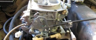
Carburetor repair VAZ 2107
Repairing a carburetor is considered a rather complicated procedure. Any operation requires care and precision. Moreover, to avoid contamination from entering the carburetor, all work must be carried out under virtually sterile conditions.
For self-repair, you will need a repair kit - a factory-prepared set of materials and parts necessary for the work. There are two types of standard repair kit:
- Full. Includes absolutely all possible elements that may be required to replace failed parts. It is usually purchased during major repairs or other serious faults.
- Incomplete. Allows you to carry out only one repair operation (for example, replacing jets).
It is more profitable to buy incomplete repair kits, since you can select only those kits that are really needed.
When repairing a VAZ 2107 carburetor, you will need a standard set of tools and a carburetor cleaner, which can be purchased at any auto store.
Carburetors become dirty quickly. In a relatively short time, jets, channels and other small elements can become clogged with dust and impurities in the fuel. The moving parts of the device wear out quickly during aggressive driving. This primarily concerns sealing gaskets.
Typically, the carburetor repair process consists of disassembling, washing all parts, replacing worn and damaged elements, and reassembling.
Recommendations before repair
Before starting repair work, you should pay attention to the following points.
- Work should be carried out on a cold engine to avoid the possibility of burns.
- You need to make sure that there is little fuel left in the system. Otherwise, most of the gasoline must be drained.
- Repairs must be carried out outside in dry weather or in a well-ventilated area (gasoline fumes can cause nausea and dizziness).
- You should prepare a clean place in advance for disassembling the carburetor and a container for washing it.
Read also: Repair instructions for Cherry Amulet
Depending on the symptoms of the malfunction, you should pay attention to individual parts and components of the carburetor:
- If the engine idles unsteadily or stalls, then the economizer valve needle is most likely worn out.
- If during disassembly water is found in the cavity, then the carburetor has lost its seal. It is recommended to check all hoses and connections.
- The appearance of a flame under the hood indicates a fuel leak. A thorough inspection of all carburetor elements and a search for gaps or holes will be required.
- If, when independently adjusting the quality and quantity screws, the engine does not react in any way to the turns of the screws, you should remove them and check whether the threads are broken.
- If the carburetor starts to “shoot”, you need to check all wires and terminals for short circuits.
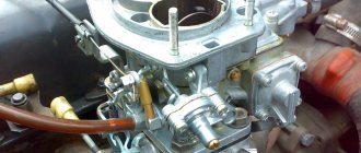
Removing the carburetor
Any repair begins with removing the carburetor mechanism from the car. Dismantling the device is carried out strictly according to the following scheme:
- Disconnect power from the battery.
- Remove the air filter housing (it prevents access to the carburetor).
- Disconnect all fuel and air supply hoses from the carburetor.
- Unscrew the bolts securing the carburetor to the body. If the bolts do not come out, you can apply WD-40 water repellent to them.
- Place the removed carburetor on a flat surface and clean it of dirt and gasoline stains.
Video: how to quickly remove a carburetor from a car
The procedure for repairing a VAZ 2107 carburetor
To repair a particular carburetor component, you will need to disassemble the entire device, thoroughly wash all parts, dry them, inspect them and decide on replacement or adjustment. First, place the removed carburetor on a clean, level surface. Next you need to perform the steps in the following order.
- Remove the return spring.
- Using a Phillips screwdriver, remove the screw securing the three-arm lever.
At this point, disassembling the carburetor is considered complete. Metal parts are washed from carbon deposits and dirt with acetone or a special liquid for cleaning carburetors and dried with a stream of compressed air. Gaskets and other rubber elements are replaced with new ones.
All components will need to be checked for integrity - there should be no visible signs of wear or mechanical damage . Installation of new parts is carried out in the reverse order of disassembly. In any case, the following must be replaced:
- accelerator pump diaphragms;
- return springs;
- fuel valve mechanism;
- all rubber seals;
- most paronite gaskets.