A modern car is now equipped with a variety of active safety systems, the list of which is growing every year. These also include a system to prevent wheel locking during braking - ABS (Anti-lock braking system).
ABS is one of the very first safety systems that began to be used on a car, and it is now found on almost all cars, from budget categories to premium ones.
Let's briefly consider the purpose of ABS - this system is needed so that the wheels do not lock during braking, but continue to rotate, albeit at a slower rate.
Thanks to this, the grip of the wheel on the road surface is not lost and the likelihood of the car skidding is completely eliminated, the car remains fully controlled by the driver.
ABS has been used in vehicles for a long time and has proven its effectiveness more than once.
This system works simply. There is an electronic unit that controls the deceleration rate of each wheel. And if one of them stops faster than others, the block reduces the force of fluid pressure in the brake caliper on this particular wheel, that is, the brake mechanism begins to act less.
You can read more about the ABS device and other information on this system here.
What is the ABS sensor for?
It is stated above that the ABS unit, popularly called the “brains” of the braking system, controls the speed of rotation of the wheels, so the design of this system could not be done without sensors.
They are the “sense organs” of this system and based on their readings the ABS functions.
The first anti-lock braking system used only one sensor, which was installed in the axle of rear-wheel drive cars.
But as ABS has improved, their number has increased; modern cars already use 4 sensors. This allows the system to monitor the rotation speed of each wheel individually.
Types of sensors
There are three types of such elements, differing in their operating principle. The most common passive sensors are induction type.
The essence of their work comes down to a change in voltage due to the influence of a magnetic field. Their main disadvantage is the inability to determine the speed of rotation of the wheel at very low speeds.
The remaining two types are active.
One of them is magnetoresistive (rare). The principle of its operation is based on the magnetoresistive effect - the property of a semiconductor to change the trajectory of electrons when exposed to a magnetic field.
The second type of active sensor uses the Hall effect, in which electrons on a semiconductor wafer move to its edges when the magnetic field changes.
Checking the sensor without instruments
The most crude way to check the health of the sensor is to test the magnetic field created during operation of the device. To do this, a steel object is applied to the sensor, which should be attracted when the ignition is turned on.
It is possible to visually inspect the device for cracks in the housing or noticeable breaks and oxidation in the wiring. It is recommended to inspect the plug and the condition of the contacts in it; oxidation is the cause of deterioration in signal conductivity.
Sensor Features
There are several significant differences between passive and active types. They are called passive because they do not require voltage to operate; such a sensor itself generates electrical impulses, to which the electronic unit reacts. Active elements require voltage to be applied to them.
Passive elements are very simple in design and are very reliable. That's why they are so common, despite their shortcomings.
Active types of sensors use microcircuits in the design, which complicates the element and makes it more vulnerable. But they are highly accurate and do their job even at low speeds.
Since all types of sensors operate under the influence of a magnetic field, it alone is not enough in the design; another element is needed to which it would react.
The induction (passive) type uses a ferromagnetic alloy pulse gear ring mounted on the drive hub or shaft, as well as on the steering axle. Previously, it could also be mounted on the bevel gears of the main drive.
In active types, a magnetic pulse ring is used. In the case of a magnetoresistive sensor, this ring is divided into alternating sectors with permanent magnets of different polarities.
But the Hall sensor uses a regular magnetic ring, without any sectors, integrated into the wheel bearing.
How to fix problems
After checking with instruments and identifying the faulty unit, you can begin repairs. Some owners repair the sensors by replacing the wiring harness or rewinding the coil.
Sensor failure
A faulty passive type sensor can be repaired yourself:
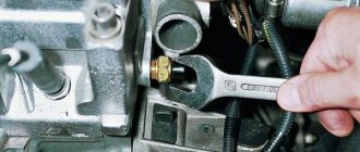
- Remove the sensor from the hub. The fastening bolt often becomes sour, so you should unscrew it carefully. For removal it is allowed to use WD40 type fluid.
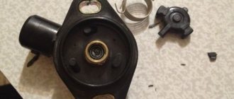
- Remove the protective coil housing. Removal is done with a file. The cut should be done extremely carefully so as not to damage the housing and winding.
- Remove the protective film from the winding by prying it off with a sharp knife.
- Carefully unwind the wire from the spool. During the removal process, the version of a conductor break is confirmed. As a result, you will be left with an empty ferrite core, resembling a spool of thread in shape.
- Wind a new winding. Copper wire from the coils of common relays of the RES-8 type can be used as a conductor. Winding can be done using a drill with smooth speed control. Be careful as breaking the wire will return you to the start. It is recommended to wind the conductor to the top level of the coil.
- Check resistance. Most coils have a value in the range of 0.9-1.2 kOhm. To clarify, it is recommended to measure the parameter on a known-good sensor located on the opposite side of the axis. The resistance is adjusted by unwinding the excess wire. If the reading is low, you will need to use another wire or re-wind. Secure the wire from unraveling with tape or other adhesive tape.
- Solder the wires to the coil terminals that serve as a connection between the winding and the harness. For outputs, it is recommended to use multi-core insulated cable, which has increased strength.
- Install the coil into the old housing. If it received significant damage when disassembling the device, then the coil is filled with epoxy resin. To do this, the part is located in a metal container of a suitable size, for example, a capacitor housing. The air gap between the coil and the glass is carefully filled with resin. When pouring, it is advisable to avoid large air voids. After the resin has completely hardened, the body is removed.
- Reinstall the sensor mount, securing it with epoxy resin. Conduct a visual inspection of the product for cracks and voids in the insulation. Detected defects are filled with resin.
- Place the repaired sensor in its original place and check the functionality of the ABS system. When installing the device, it may be necessary to modify the resulting body, which is done with a file and sandpaper. The field installed sensor should have a gap between the coil and the toothed ring within 0.9-1.1 mm. When reducing the gap, it is recommended to bring it up to standard by installing gaskets.
It is necessary to drive the car for some time, checking the operation of the brakes at different speeds. There are cases when the ABS spontaneously activates at certain wheel speeds - usually just before stopping. Then you will need to search for the gap, adjusting it with shims or sharpening the sensor body.
Another repair option is to install a modified crankshaft position sensor from domestic cars:
- Remove the “original” sensor and modify the body of the “donor” part. Most often, this role is played by the DPKV from the ZMZ-406 engine, which has a resistance within 800 Ohms. When modifying, you should strive to ensure a parallel arrangement of the core with the wound coil and the toothed ring mounted on the axis. The gap between the sensor and the ring should be within 0.2-0.3 mm.
- Test the operation of the device. On some Japanese-made cars, the ABS lamp may turn on periodically. The situation is corrected by changing the connection of the harness contacts.
Both options for repairing the sensor require perseverance and the ability to work with various tools from the owner. If the car user doubts his abilities, it is recommended to purchase a new device or find the product at a car dismantling site.
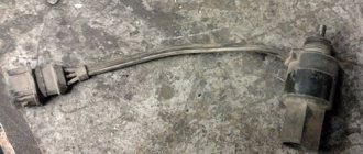
Wiring problem
If the problem of sensor loss of functionality lies in the wiring, then it can be replaced:
- Unscrew the sensor mount to the wheel hub.
- Disconnect the wire plug.
- Remove the sensor along with the wire. This will require removing the mounting brackets installed on the wiring.
- Measure the installation distances of the brackets. It is recommended to draw a diagram and photograph the factory location of the fasteners.
- Cut the sensor from the wire, leaving some extra length for soldering.
- Check the integrity of the remaining cable on the sensor. If the section is intact, then you can begin installing a new wiring segment.
- Remove all protective covers and fastenings from the old cable.
- Select a wire with a suitable outer diameter and cross-section.
- Install the previously removed protection and fastening elements onto the new harness. To facilitate assembly, it is recommended to use a soap solution.
- Solder the sensor and plug into place.
- Carefully isolate the joint. The accuracy of operation and service life of the repaired part depend on the tightness of the connection.
- Reinstall the sensor, check the functionality of the ABS system, and make sure there are no errors during operation.
Inductive type element design
Since inductive sensors are the most common, their design will be considered in the future.
Such a sensor consists of an inductive coil, inside of which a magnetic core is placed. It is installed next to the toothed impulse ring, but so that there is a certain gap between them.
When the wheel rotates, the ring teeth pass through the magnetic field created by the core, which affects the magnetic flux, causing the alternating voltage value in the coil winding to change.
As a result, the speed of rotation of the wheel, and with it the pulse ring, affects the frequency and amplitude of oscillations of the output voltage on the coil. These parameters are fed to the “brains”, as a result of which they estimate the speed of deceleration of the wheel.
Problems with at least one of the ABS sensors can lead to a complete shutdown of the system. And although the braking system on the car will work, you can forget about the braking efficiency and safety that ABS provided.
Sensor types
There are two types of sensors on cars:
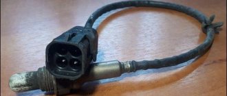
- passive sensor built on the basis of a coil;
- active sensor that uses the Hall effect.
The passive sensor turns on after the start of movement and reads data from the toothed pulse ring. The passage of a tooth past the device causes the generation of a current pulse, which is read by the control unit. The sensors start working at speeds above 5 km/h and do not respond to contamination.
The active sensor consists of electronic components and a permanent magnet, which is mounted on the hub. When the magnet rotates in the device, a potential difference arises, which is formed into a microcircuit control signal. The information is then sent to the block. Sensors of this design are rare and cannot be repaired.
Causes of sensor malfunction
The induction sensor is characterized by its simple design and high reliability; malfunctions with it occur very rarely. The problem most often lies in the wiring through which signals are sent to the control unit.
Since the sensors and their wiring are located directly next to the wheels, over time the circuit may break or short out. Often, sensor failures occur due to oxidation of the contacts.
Due to the fact that after turning on the ignition on a car, ABS always undergoes self-diagnosis, during which the condition of all elements of the system is assessed, it is quite simple to identify problems with the sensors; if they occur, the warning light will constantly light up on the dashboard.
In total, there are 4 types of system behavior when a malfunction is detected:
- Self-diagnosis detects an error and ABS is disabled. This may be a sign of an error in the control unit, or a break in the wiring coming from the sensor;
- The system undergoes diagnostics, during which no problems are detected, but after this the ABS is turned off. This result usually results from problems with the wiring going to the sensors (oxidation, open circuit, short circuit, etc.);
- Self-diagnosis detects an error, but the system does not turn off and continues to operate. This usually indicates a break in the wiring on one of the sensors;
- ABS does not turn on. This can happen due to a broken wiring, or because the impulse ring is damaged, chipped or broken. This result can also be produced by a heavily worn hub bearing, which is why there is significant play in it.
Since malfunction of ABS often occurs due to wiring, it is quite simple to identify a faulty element and all you need is a multimeter.
Of course, it is better to check using an oscilloscope, since such a device makes it possible to visually assess the amplitude and frequency of voltage fluctuations in the sensor, but not everyone has one.
Next, we’ll figure out how to check the ABS sensor on different cars, although in general the procedure is the same, despite the fact that any type of sensor can be used on different models.
Symptoms of a problem
To monitor the operation of the system, there is a yellow or orange indicator light. In normal conditions, when the ignition is turned on, a lamp on the instrument cluster is activated, then self-diagnosis of system elements is carried out and the icon automatically goes out.
Signs of breakdown of ABS system elements:
- turning on the system warning lamp while driving;
- stable wheel locking during heavy braking;
- absence of sounds indicating ABS operation (brake pedal vibration);
- the appearance in the memory of the electronic system of error codes related to the ABS.
If signs of ABS malfunction appear, operation of the vehicle is prohibited. The brakes, designed to work together with the anti-lock braking system, do not work correctly when it is turned off.
Check on Ford Focus 2
First, let's look at how the test is carried out on a Ford Focus 2. This car uses a Hall effect sensor and is located in the upper part of the wheel hub. It is easy to detect - just remove the wheel, unscrew and move the caliper to the side, and also remove the brake disc.
Before starting the inspection, be sure to check the tire pressure. It must be the same in all wheels, otherwise the pressure difference may affect the performance of the system.
To check the sensor on Focus 2, for ease of access, you should jack up and remove the wheel from the side being tested.
Next, disconnect the block of wires coming from the sensor. We visually assess the condition of the braid and wires; they should not show abrasions or other types of damage.
At the first stage, we check the resistance. To do this, switch the multimeter to ohmmeter mode and connect its probes to the terminals in the block.
On Focus 2, the sensor resistance when measured should be in the region of 1.3-1.4 kOhm.
But there is one nuance that is important to consider. During measurements, you should knead the wire, especially at bends.
The fact is that at the point where the wire is broken, the copper conductors can come into contact, and therefore the sensor can show normal resistance. And during crumpling and bending, contact is broken.
If the readings do not match, a measurement should be taken at the input of the wires to the sensor. This will reveal whether the problem lies in the sensor itself, or just in the wires.
If, when checking the resistance near the element, a discrepancy in resistance remains, then the sensor must be replaced.
In some cases, the cause of the problems lies in contamination of the semiconductor platinum of the Hall element. Therefore, you should remove the sensor itself and clean it.
In addition to the sensor wiring, you should also check the entire circuit for damage. To do this, you need to disconnect the wire block from the control unit.
Then we find out from the technical documentation for the car which terminals on the block correspond to which sensor, after which we connect a multimeter to the necessary connectors and measure the resistance.
If it does not meet the required parameters, you should look for a break in the area from the control unit to the sensor connection block.
Faults such as breaks or short circuits can be treated by replacing the wires. But if the element itself malfunctions, it is replaced.
Ways to check functionality
To determine the condition of a part, we will perform a series of steps to diagnose it, moving from simple to complex:
- Let's check the fuses by opening the unit (inside the passenger compartment or in the engine compartment) and inspecting the corresponding elements (indicated in the repair/operation instructions). If a burnt component is found, we will replace it with a new one.
- Let's inspect and check:
- integrity of connectors;
- wiring for abrasions that increase the risk of a short circuit;
- contamination of the part, possible external mechanical damage;
- fixation and connection to ground of the sensor itself.
If the listed measures do not help to identify a device malfunction, it will have to be checked using instruments - a tester (multimeter) or an oscilloscope.
Tester (multimeter)
This method of diagnosing the sensor will require a tester (multimeter), instructions for operating and repairing the car, as well as PIN - wiring with special connectors.
The device combines the functions of an ohmmeter, ammeter and voltmeter
Tester (multimeter) is a device for measuring electric current parameters, combining the functions of a voltmeter, ammeter and ohmmeter. There are analog and digital device models.
To obtain complete information about the performance of the ABS sensor, you need to measure the resistance in the device circuit:
- We lift the car with a jack or hang it on a lift.
- Remove the wheel if it prevents access to the device.
- Remove the cover of the system control unit and disconnect the controller connectors.
- We connect the PIN to the multimeter and the contact socket of the sensor (the connectors for the rear wheel sensors are located inside the cabin, under the seats).
We connect the PIN to the tester and the contact socket of the sensor - We measure the resistance (tester in ohmmeter mode) at the contacts of the device. We compare the readings of the device with the car’s operating manual, where the required parameters should be indicated.
- We check the electrical circuit by ringing the sensor wiring for a possible short circuit.
- We spin the wheel manually and at the same time measure the resistance - the tester readings should change depending on the rotation speed.
- We switch the tester to the “voltmeter” mode and measure the voltage on the sensor - we turn the wheel at a frequency of 1 rev/sec, monitoring the readings of the device. Voltage parameters from 0.25 to 1.2 V are considered optimal, but it should be taken into account that increasing the wheel speed necessarily increases them.
The device readings must correspond to the data specified in the repair and operation manual for a particular vehicle. If the device resistance:
- below the minimum threshold - the sensor is faulty;
- approaches zero - short circuit;
- unstable (jumping) at the moment of twitching of the wire - a violation of contact inside the wiring;
- infinity or no readings - wire break.
Attention! The resistance of the ABS sensors on the front and rear axles is different. The operating parameters of the devices are 1–1.3 kOhm in the first case and 1.8–2.3 kOhm in the second.
Video “Diagnostics of the ABS sensor”
How to check using an oscilloscope (with connection diagram)
In addition to self-diagnosis of the sensor with a tester (multimeter), it can be checked using a more complex device - an oscilloscope.
The device examines the amplitude and time parameters of the sensor signal
An oscilloscope is a device that studies the amplitude and time parameters of a signal, which is intended for accurate diagnosis of pulse processes in electronic circuits. This device detects problems with connectors, broken connections to ground, and broken conductors. The test is performed by visually observing the vibrations on the device display.
To diagnose the ABS sensor with an oscilloscope, you must:
- Fully charge the battery so that during the measurement you can observe voltage drops (jumps) on the connectors or conductors.
- Find the touch sensor and disconnect the upper connector of the part.
- Connect an oscilloscope to the contact socket.
Connecting the device to the ABS sensor connector (1 - toothed disc-rotor; 2 - sensor) - Rotate the suspended wheel (by lifting the car on a jack or lift) at a constant frequency of 2-3 revolutions per second.
- Detect the amplitude of signal oscillations on the device display.
- Rotate the second wheel of the axle and similarly detect vibrations.
The serviceability of the ABS sensor is indicated by:
- equal amplitude of signal fluctuations when the wheels of one axle rotate;
- absence of amplitude beats when diagnosing with a sinusoid signal of lower frequency;
- maintaining a stable, even amplitude of signal fluctuations not exceeding 0.5 V when the wheel rotates at a frequency of 2 rps.
Note that an oscilloscope is a rather complex and expensive device. Modern computer technologies make it possible to replace this device with a special program downloaded from the Internet and installed on a regular laptop.
Video “Laptop instead of an oscilloscope”
Checking a part without instruments
The easiest way to diagnose a device without instruments is to check the magnetic valve on the induction sensor. Any metal product (screwdriver, wrench) is applied to the part inside which the magnet is installed. If the sensor does not attract it, it is faulty.
Most anti-lock brake systems of modern cars have a self-diagnosis function with errors displayed (in alphanumeric encoding) on the on-board computer screen. You can decipher these symbols using the Internet or the machine’s operating instructions.
Diagnostic features for BMW E39
Next, let's look at the nuances of checking the ABS sensor on a BMW E39. This car already uses an induction element.
Diagnostics are carried out using the same methods as for Focus 2. That is, the resistance of the sensor, its wiring, as well as the circuit from the control unit are checked.
Since this car uses an induction type element, it is additionally possible to measure the output voltage.
To do this, switch the multimeter to voltmeter mode and connect it to the sensor wiring connectors.
Next, spin the wheel to approximately 50 rpm. In this case, the element being diagnosed will begin to generate electricity, the voltage of which should be around 2 V.
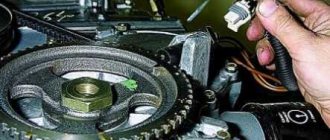
Design nuances of Lada "Priora", "Kalina"
Now let’s figure out a little how to diagnose and replace Lada cars of the Priora and Kalina models. These cars were taken as an example because they use drum brakes at the rear, and above we looked at how work is carried out with sensors that work with disc mechanisms.
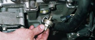
Checking the sensors on Kalina or Priora is completely identical to those described. But this sensor still needs to be found. The element is installed in the rear wall of the hub, and the impulse ring is located inside the mechanism, under the drum.
Therefore, in order to assess its condition, you will have to remove the drum from the car, and immediately under it you will see the ring, as well as the protruding part of the sensor, which passes through the technological hole in the brake pad.
That is, by checking the condition of the ring, you can immediately look at and clean the sensor itself from dirt. And then we measure the resistance of the sensor and the entire circuit up to the “brains”.
Features of the Opel Vectra sensor
Now let's go over the features of the Opel Vectra. And the main one lies in the fact that this sensor is made in the form of a ring and is mounted on the hub. Therefore, it is not difficult to check it again using a multimeter, but replacing it in case of damage is difficult, since you will have to remove the hub.
In general, by simply measuring the resistance, you can assess the condition of any ABS sensor, as well as its wiring.
Whatever element is used on the car, its resistance will vary in the range of 1.2-1.8 kOhm.
One of the main conditions for diagnostics is not only the resistance value, but the same resistance reading on all sensors.
Label: Sensors