Information on the “five” schemes is intended for self-repair of a car in case of minor problems with electrical equipment. The electrical circuits are divided into several blocks (for ease of viewing via a computer or phone), there are files in the form of a single picture with a description of each element - for printing on a printer. Years of production of this model: from 1979 to 2010. At the end of December 2010, AvtoVAZ stopped producing it due to low demand for the VAZ-2105 model. By this time, 2 million cars had already been produced.
Scheme of carburetor VAZ 2105
This is a color diagram of the electrical equipment of the VAZ 2105. At the top of the image on the right are the colors of the wires, at the bottom are the designations of the elements.
1 – block headlights, 2 – side direction indicators, 3 – battery, 4 – starter activation relay, 5 – electro-pneumatic valve for the carburetor forced idle economizer, 6 – starter, 7 – carburetor microswitch, 8 – generator 37.3701, 9 – headlight cleaners , 10 – sound signals, 11 – spark plugs, 12 – engine compartment lamp, 13 – oil pressure warning lamp sensor, 14 – coolant temperature indicator sensor, 15 – ignition distributor, 16 – brake fluid level sensor, 17 – ignition coil, 18 – windshield wiper, 19 – electric headlight washer motor, 20 – electric windshield washer motor, 21 – control unit for the electro-pneumatic valve of the carburetor forced idle economizer, 22 – ignition switch, 23 – ignition relay, 24 – relay-interrupter for direction indicators and hazard warning lights, 25 – reverse light switch, 26 – brake light switch, 27 – windshield wiper relay, 28 – mounting block, 29 – socket for portable lamp, 30 – glove box lighting lamp, 31 – VAZ-2105 cigarette lighter, 32 – heater fan electric motor, 33 – parking brake warning lamp switch, 34 – carburetor air damper warning lamp switch, 35 – three-lever switch, 36 – hazard warning switch, 37 – instrument lighting switch, 38 – external lighting switch, 39 – lamp switches located in the door pillars, 40 – fog light circuit fuse, 41 – oil pressure warning lamp, 42 – rear fog light switch, 43 – fuel reserve warning lamp, 44 – instrument cluster, 45 – battery charging warning lamp, 46 – breaker relay parking brake warning lamp, 47 – interior lamps, 48 – parking brake warning lamp, 49 – carburetor air damper warning lamp, 50 – warning lamp block, 51 – rear fog light warning lamp, 52 – rear window heating warning lamp, 53 – brake fluid level indicator lamp, 54 – voltmeter, 55 – side light indicator lamp, 56 – turn signal indicator lamp, 57 – speedometer 2105, 58 – headlight high beam indicator lamp, 59 – heater fan switch, 60 – rear window heating switch, 61 – additional resistor for the heater electric motor, 62 – plug connector for connecting the bar, 63 – rear lights, 64 – license plate lights, 65 – fuel gauge sensor, 66 – rear window heating element.
Wiring diagram 2105 - full view:
VAZ 2104 fuses
The fuses of the VAZ Four, as in any other car, are designed to open the electrical circuit they protect as a result of the burnout of a special insert. Destruction occurs when the current for which the protective element is designed is exceeded. The current strength of the fuse is selected depending on the permissible load in the circuit it protects and depends on the consumers connected to it. If an emergency situation occurs, the fuse link must first fail, stopping the current supply and saving the machine from fire. The fuse fails for several reasons:
- short circuit, which is possible if the wire insulation is damaged or electrical appliances are installed incorrectly;
- the fuse rating does not match the circuit in which it is installed. This is possible if you incorrectly install a fuse-link designed for a lower current.
Since the performance of all vehicle consumers depends on the condition of the fuses, it is worthwhile to dwell in more detail on their replacement, search and solution of possible problems.
Second version of the scheme
- block headlights
- side turn signal repeater
- battery
- lamp relay for monitoring battery charging
- electropneumatic valve
- carburetor microswitch
- generator
- headlight glass cleaner
- sound signal
- starter
- engine TDC indicator lamp
- engine compartment lamp
- oil pressure warning light sensor
- coolant temperature gauge sensor
- fluid level sensor in the hydraulic brake reservoir
- candles
- windshield washer pump motor
- distributor cap
- distributor
- ignition coil
- electric motor of the pump serving the headlight washers
- electronic control unit
- diagnostic block (installed on some cars)
- windshield wiper relay
- relay-interrupter for direction indicators and hazard warning lights
- wiper motor
- brake light switch
- electric motor of the heater (stove)
- additional resistance
- portable lamp socket
- reverse light switch
- Handbrake warning lamp switch
- relay and fuse box
- low beam headlight relay
- headlight high beam relay
- horn relay
- Relay for windshield wipers and headlight washers
- rear window defroster relay
- glove compartment lamp
- cigarette lighter
- dome light switches
- interior lamp
- rear window defroster switch
- hazard warning switch with warning lamp
- warning lamp block
- rear fog light warning lamp
- hand brake warning lamp
- warning lamp indicating a drop in brake fluid level
- windshield wiper and washer lever
- handbrake warning lamp relay
- horn switch
- outdoor light switch
- turn signal switch
- headlight switch lever
- egnition lock
- instrument light switch
- rear fog light switch
- instrument cluster
- warning lamp indicating insufficient oil pressure
- fuel reserve warning lamp
- fuel level indicator
- battery charging warning light
- water temperature indicator
- instrument lighting lamps
- voltmeter
- speedometer
- indicator lamp for turning on external lighting
- turn signal indicator lamp
- high beam warning lamp
- three-position heater fan switch
- rear window defroster
- fuel level and reserve indicator sensor
- rear light block
- license plate lights VAZ 2105
How to make a replacement
Sometimes fuses require replacement, even if the circuit they protect is in good condition. The fuse rating is calculated accurately enough so that if the current consumption increases even by several tens of percent, additional damage will not be caused to the car.
But a short-term increase in the current flowing through the fuse is quite possible even in normal situations. Inrush current in electric motors, increased consumption by lamps when the filaments heat up, overheating of the fuse housing due to poor contact in its connector, and finally, manufacturing defects and increased nominal tolerances. Sometimes it can even be due to natural aging, as well as an installation error.
The block cover is installed on a plastic latch. Not very convenient, but it is quite possible to open it. The main thing is not to forget to close it later, since electrical appliances really do not like dirt and moisture.
There is a notice on the inside of the lid that indicates where each device is located and its operating current. This data must strictly correspond to reality, otherwise the above-mentioned troubles are possible. The new type of fuses are usually made of transparent plastic, which makes it possible to determine their integrity even visually. But not always. Sometimes the break cannot be seen with the eye. You can use a multimeter in ohmmeter mode or a test light.
The easiest way is to measure the resistance of the removed fuse with an ohmmeter. The device should show a resistance of about zero. No more than his own readings with the probe tips short-circuited among themselves. You can compare it with a known-good fuse in stock.
A certain convenience is the color coding of denominations. But you shouldn’t trust it blindly; the main thing is the number indicated on the end of the case. The new insert must be marked in the same way as the diagram allows, since the failed insert could also be selected incorrectly.
If the new fuse also fails, further replacements are pointless. It is necessary to look for and eliminate faults in the instruments, instrument panel or wiring itself.
Scheme of VAZ-21053 with generator 37.3701
1 — block headlights; 2 — side direction indicators; 3 - battery; 4 — starter activation relay; 5 — carburetor electro-pneumatic valve; 6 — carburetor microswitch; 7 - generator 37.3701; 8 — gearmotors for headlight cleaners*; 9 — electric motor of the engine cooling system fan*; 10 — fan motor activation sensor*; 11 — sound signals; 12 — ignition distributor; 13 — spark plugs; 14 — starter VAZ-2105; 15 — coolant temperature indicator sensor; 16 — engine compartment lamp; 17 — oil pressure warning lamp sensor; 18 — ignition coil; 19 — brake fluid level sensor; 20 — windshield wiper gearmotor; 21 — carburetor electro-pneumatic valve control unit; 22 — electric motor of the headlight washer pump*; 23 — electric motor of the windshield washer pump; 24 — brake light switch; 25 — windshield wiper relay; 26 — instrument lighting regulator; 27 — relay-breaker for alarm and direction indicators; 28 — reverse light switch; 29 — plug socket for a portable lamp**; 30 — cigarette lighter; 31 — glove box lighting lamp; 32 — mounting block (a jumper is installed instead of a short-circuit relay); 33 — lamp switches on the front door pillars; 34 — lamp switches on the rear door pillars; 35 — lampshades; 36 — parking brake warning lamp switch; 37 — switch for the carburetor air damper warning lamp; 38 — alarm switch; 39 — three-lever switch; 40 — ignition switch; 41 — ignition relay; 42 — external lighting switch; 43 — rear fog light switch; 44 — fog light circuit fuse; 45 — oil pressure warning lamp; 46 — instrument cluster; 47 — fuel reserve warning lamp; 48 — fuel level indicator; 49 — battery charge indicator lamp; 50 — coolant temperature indicator; 51 — control lamp for the carburetor air damper; 52 — parking brake warning lamp; 53 — control lamp block; 54 — rear fog light indicator lamp; 55 — control lamp for heated rear window; 56 — brake fluid level warning lamp; 57 - voltmeter; 58 — speedometer; 59 — control lamp for external lighting; 60 — turn signal indicator lamp; 61 — control lamp for high beam headlights; 62 — heater fan switch; 63 — rear window heating switch with backlight*; 64 — block for connecting the bar; 65 — heater fan electric motor; 66 — additional resistor of the heater electric motor; 67 — rear lights; 68 — pads for connecting to the rear window heating element; 69 — sensor for level indicator and fuel reserve; 70 — license plate lights.
Useful: Diagram of Lada Kalina VAZ-1117, VAZ-1118, VAZ-1119
How to check the VAZ 2107 starter relay
To check the functionality of the relay, you need a voltmeter or “control”. The functionality check is performed as follows:
- remove the wire block from the relay; check whether the contacts on the relay and the block are oxidized;
- clean contacts if necessary;
- make sure there is ground on the wire going to contact “86” of the relay;
- check whether voltage appears on the wire going to terminal “85” of the relay if you try to start the car with the key;
- make sure that when the ignition is turned on, voltage is supplied to the wire going to terminal “30”;
- if there is voltage at the terminals, the problem is in the relay, not in the power supply;
- remove the starter relay from the car;
- make sure that when voltage is applied to terminals “85” and “86”, the contact between “30” and “87” relay terminals is closed.
If the relay does not operate, it must be replaced with a new one.
VAZ 2105 injector diagram
1 – electric motor of the engine cooling system fan; 2 – mounting block; 3 – idle speed regulator; 4 – electronic control unit; 5 – octane potentiometer; 6 – spark plugs; 7 – ignition module; 8 – crankshaft position sensor; 9 – electric fuel pump with fuel level sensor; 10 – tachometer 2105; 11 – control lamp “CHECK ENGINE”; 12 – car ignition relay; 13 – speed sensor; 14 – diagnostic block; 15 – nozzle; 16 – adsorber purge valve; 17, 18, 19 – injection system fuses; 20 – ignition relay for the injection system; 21 – relay for turning on the electric fuel pump; 22 – intake pipe electric heater relay; 23 – electric heater of the intake pipe; 24 – intake pipe heater fuse; 25 – oxygen concentration sensor; 26 – coolant temperature sensor; 27 – throttle position sensor; 28 – air temperature sensor; 29 – absolute pressure sensor;
- A – to the “plus” terminal of the battery;
- B – to terminal “15” of the ignition switch;
- P4 – relay for turning on the fan motor.
A FEW WORDS ABOUT THE NEW PRODUCT
The modernized unit completely coincides with the old product in all respects, the diagram of the VAZ 2105 mounting block of the new model is no different from previous releases. Its main difference is that fuses of a new type began to be used. Cylindrical products were replaced by blade fuses. They have a larger contact area, so their reliability during operation increases. They are standard and used on many modern cars.
The figure shows a new block, where its differences from the old product are clearly visible. It is installed in the regular place of the old unit. Connectors with wires are connected in the engine compartment from the bottom of the block, and the second part will be installed from the passenger compartment, in the area of the glove box. It is impossible to mix up the connectors, since each of them is equipped with its own color mark.
Article on the topic: Do-it-yourself replacement of front silent blocks on a VAZ 2110
To make it easier to determine their rating, fuses of a new type are marked in different colors. So, for example, products for a current of 7.5 Amperes are painted brown, red was assigned to 10 Amperes, and blue belongs to products with a rated current of 15 Amps. The most powerful current products will be yellow. On “fives” and “sevens” they use products with a rating of 10 and 20 Amps.
In retail chains, mounting blocks of these and “Avar” are sold. They are completely interchangeable with each other and with old products. Their cost can range from 1800 to 2000 rubles.
Fuse and relay diagram 2105
Until 1988, the fog lamps in the rear lights and the fog lamp warning lamp were protected by fuse 17 of the mounting block. Since 1988, they began to be protected by a separate fuse, which is located in a plastic case in the wiring harness near the car's fog light switch.
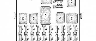
Mounting block 2105-3722010-02
Mounting block 2105-3722010-08
Mounting block diagram 2105-3722010-08
K1 Relay for turning on the heated rear window K2 Relay for turning on the headlight washer cleaners K3 Relay for turning on the sound signal (jumper) K4 Relay for turning on the electric fan motor K5 Relay for turning on the high beam headlights K6 Relay for turning on the low beam headlights
Circuits protected by fuses
F1 (10A) Reversing lamps. Heater electric motor. Rear window heating indicator. Rear window heating relay (winding). F2 (10A) Wiper motors. Windshield washer pump motors. Windshield wiper relay. Relay for cleaners and headlight washers (contacts). F3 (10A) Reserved. F4 (10A) Reserved. F5 (20A) Rear window heating element. Relay for turning on the heated rear window (contacts). F6 (10A) Cigarette lighter. Watch VAZ-2105. F7 (20A) Sound signal. Horn relay. Radiator cooling fan electric motor. Radiator cooling fan motor activation relay (contacts) F8 (10A) Direction indicators (in hazard warning mode). Turn signal indicator (in hazard warning mode). Relay-breaker for direction indicators and hazard warning lights. Hazard warning switch with warning lamp. F9 (7.5A) Rear fog lamps. Indicator for switching on the rear fog lamps. F10 (10A) Direction indicators (in turn indication mode). Turn signal interrupter relay. Turn signal indicator. Tachometer. Fuel indicator. Fuel reserve indicator. Parking brake indicator. Indicator of insufficient oil pressure in the engine lubrication system. Coolant temperature gauge. Voltmeter. Indicator of emergency condition of the working brake system. Battery charge indicator. Electric fan relay. Generator excitation winding (generator 37.3701). F11 (10A) Interior lamps. Brake light bulbs. Luggage compartment lamps. F12 (10A) High beam headlights (right headlight). F13 (10A) High beam headlights (left headlight). High beam indicator. F14 (10A) Front side light (left headlight). Rear marker light (right light). License plate lights. Indicator for turning on side lights. F15 (10A) Front side light (right headlight). Rear marker light (left light). Cigarette lighter lamp. Instrument lighting lamp. Glove box lighting lamp. Clock (lighting lamp). F16 (10A) Low beam headlights (right headlight). Headlight wiper relay (relay coil). F17 (10A) Low beam headlights (left headlight).
In the old-style VAZ 21053, the unit is located directly under the dashboard next to the left door, that is, inside the cabin. In the new VAZ 21053, the safety block is located outside under the hood, closer to the windshield, on the driver's side. The latest models of the “five” are most often equipped with an external fuse block. To open the unit, you need to remove the cover by pushing it upward. On any cover there is a diagram of the VAZ mounting block, which reflects the location of the fuses with a description of the electric current for each of them. In older VAZ 2105 models, the most precise installation of each fuse in accordance with the required current strength is important.
Reasons for blown fuses
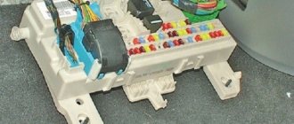
This is what the mounting block looks like
There may be several reasons for the combustion of the VAZ 2105 mounting block. One of the most common is the destruction of a certain electrical part in the car. In addition, if the electrical wiring is shorted, there may be a failure in the electricity supply, as a result of which the VAZ fuse box may also burn out. The violation process can be identified in the shortest path with a low value.
Even from the school curriculum, many remember Ohm's law, which states that the current must necessarily increase if the resistance in a certain part of the electrical circuit decreases. The result of such a violation is the combustion of a special fuse link, which is located in the fuse block of the VAZ 21053. The circuit can only be opened by interrupting the connection.
Another common cause of a blown fuse box is a sudden surge in electricity. It leads to voltage overload, and a certain part working with the distributor begins to short out or jam. Thus, high electrical voltage arises inside the electric motor, which leads to blown fuses. Of course, the fuse box is needed in order to prevent some more important spare part from burning out. Therefore, its replacement is a common occurrence.
It may happen that the fuse is installed incorrectly. In this case, the shell can melt even with the slightest jump in current in the electrical wiring.
Situations cannot be ruled out when the fuse does not sit well in the block, which is why contact is sometimes lost. If the part is not installed tightly, then such a violation can cause not only the fuse to blow, but also the melting of the unit body, which will lead to its replacement.
The last reason for fuses to malfunction is simple wear. In any case, this will happen over time, since even the best detail does not last forever. The part of the fuse made of plastic is most often susceptible to melting due to heat or overload. Over time, this will cause the formation of a smaller cross section. Many people know that when heated, metal threads increase their resistance. Its increase entails a decrease in current. As a result, the device will burn out due to a sudden voltage surge.
Car modifications
VAZ-2105 . The base model was produced in 1979 with a 1.29-liter carburetor engine producing 63.6 horsepower. It was equipped with a 4-speed gearbox.
VAZ-21050 . The same model of the five, but with a 5-speed gearbox.
VAZ-21051 . Modification with a VAZ-2101 carburetor engine with a volume of 1.2 liters and a power of 58.7 horsepower, a 4-speed gearbox as in the basic version.
VAZ-21053 . Modification with a VAZ-2103 engine with a volume of 1.45 liters and a power of 71.4 horsepower. It was equipped with both 4 and 5-speed gearboxes.
VAZ-21053-20 . Modification with a VAZ-2104 injection engine with distributed injection, volume 1.57 liters and 82 horsepower. The gearbox is 5-speed.
VAZ-21054 . A special modification for the needs of no less special services, such as the traffic police, the Ministry of Internal Affairs and the FSB. It was equipped with a VAZ-2106 carburetor engine with a volume of 1.57 liters and a power of 80 horsepower. In addition, an additional gas tank and battery were installed.
VAZ-21054-20. Another special modification, but with a more powerful VAZ-21067 engine with distributed injection, 82 horsepower, which meets the Euro-3 environmental standard. The gearbox is 5-speed.
VAZ-21055 . A vehicle for taxi service was produced in a small batch with a VAZ-341 diesel engine with a volume of 1.52 liters and a power of 50.3 horsepower.
VAZ-21057 . The export version of the VAZ-21053 car was produced from 1992 to 1997 for countries with left-hand traffic, respectively, the steering wheel was located on the right. The engine complied with the Euro-1 environmental standard.
VAZ-21058 . The same right-hand drive car, based on the VAZ-21050, was produced from 1982 to 1984.
Lada Nova . Export modification of the VAZ-2105, produced mainly for the German markets. VAZ-2105 engine, 4-speed gearbox. Produced from 1981 to 1997.
VAZ-21059 . Another special modification of the car was equipped with a Wankel VAZ-4132 rotary piston engine, with a volume of 1654 cm3 and a power of 140 horsepower. This car was produced in a small batch for the needs of the traffic police, the Ministry of Internal Affairs and the KGB.
VIS-2345 . Semi-frame pickup truck, which was produced from 1995 to 2006 by VAZINTERSERVIS JSC based on modifications of the VAZ-21053 and VAZ-21054.
LADA-2105-VFTS . A sports car with a forced VAZ-2106 engine, using WEBER 45 DCOE carburetors. The engine capacity was 1.6 liters and the power was 160 horsepower at 7000 rpm. It was equipped with spur-cut 4 and 5-speed gearboxes, with cam clutches. In order to reduce the weight of the car, in 1986 the standard doors were replaced with aluminum ones.
Mounting block in the cabin
In the first VAZ 2105 models, the fuse box was located inside the car. Such a block can still be seen today in some “fives” under the instrument panel next to the left door. Each of the fuses on the block located in the passenger compartment is responsible for the same section of the electrical circuit as the corresponding fuse on the block located under the hood.
How to identify a blown fuse
If problems arise with any group of electrical equipment in the car, the likelihood that the problem is in the fuse is high, but not one hundred percent. To make sure that a fuse has failed, sometimes an external inspection is enough: if there are burnt marks on its body, most likely the fuse has burned out. This method of checking is quite primitive, and in this case it is better to use a multimeter, which allows you to diagnose the malfunction:
- by voltage;
- by resistance.
In the first case it is necessary:
- Set the multimeter to voltage measurement mode.
- Turn on the circuit being tested, such as lighting, stove, etc.
- Check the presence of voltage at the fuse terminals. If there is no voltage at one of the terminals, the fuse must be replaced.
In the second case, the multimeter is switched to resistance measurement mode, after which the tips of the device are connected to the removed fuse. If the resistance value is close to zero, the fuse requires replacement.
If the resistance value is close to zero, the fuse requires replacement
Unit dismantling and repair
The fuse box located in the passenger compartment is removed in the same sequence as that installed under the hood. It is necessary to unscrew the fasteners, remove the connectors and remove the unit. Just as in the case of the block located under the hood, repairing the mounting block installed in the cabin involves replacing fuses and restoring the tracks.
If the fuse blows on the road and you don’t have a spare at hand, you can replace it with a wire. But at the first opportunity, the wire must be removed and a rated fuse installed instead . The fuse location diagram is usually shown on the inside of the mounting block cover.
It should be remembered that there are several types of mounting blocks that do not differ from each other in appearance. The differences lie in the wiring of the tracks. When replacing a block, you need to make sure that the markings of the old and new blocks match. Otherwise, the electrical equipment will not work correctly.
I changed the mounting block in the VAZ 2105 about six months ago. When I changed it, I didn’t know that there were several types. The sellers at the car market claimed that there was only one type, and since my old one was completely falling apart, I had to take what I had. Two problems immediately appeared with the new unit: the wipers stopped working (this problem was solved by throwing a jumper from the first fuse to the second). The second problem (and the most important) is that when the car just sits with the engine turned off, it drains the battery (the charging wire, if it matters, is inserted into the 3rd slot, 1st socket, I don’t know how to say it differently, I have almost no knowledge of auto electrics at all. Completely charged in about 8 hours, it discharges to 0. The third problem (not so important) - the turn signal indicators disappeared. I went to an auto electrician, he just threw up his hands, looked at the panel and could not do anything. I threw out the old panel, as it was almost completely crumbled, not I knew that such a problem would happen, so I have nothing to compare it with.
A pedestrian
https://www.semerkainfo.ru/forum/viewtopic.php?t=2040&start=100
Old style fuse box
Old style mounting blocks use cylindrical (finger) fuses, which are installed in special spring-loaded connectors. Such connectors are not reliable and durable, which is why they cause a lot of complaints from car enthusiasts.
The old-style VAZ 2105 mounting block uses cylindrical fuses
Each of the 17 fuses located on the old-style mounting block is responsible for the same groups of electricity consumers as the corresponding fuses on the new-style block (see table above). The only difference is the rated current for which the cylindrical fuses are designed. Each plug fuse (on a new type block) has a rated current:
- 10 A corresponds to a finger fuse with a rated current of 8 A on an old-style unit;
- 20 A - 16 A;
- 7.5 A - 8 A.
Maintenance and repair of the VAZ 2105 fuse box in most cases does not cause difficulties for car enthusiasts. To independently determine the malfunction of the mounting block and fix it, even a little driving experience is enough. For reliable operation of electrical equipment, it is important to use fuses with the parameters specified in the technical documentation.
How to change fuses
It is very important to consider how to properly replace fuses before it is too late, otherwise the consequences may be completely different. It is also important to know how to change the ignition relay
It must be remembered that in this case there is no difference between the concept of carburetor and VAZ-2107 injector.
In order to replace the fuse, you first need to open the hood and find where it is located. First you need to turn off the ignition system of the VAZ-2107 and disconnect the battery itself from the power supply. The latches must be released. They are located on the sides of the lid, which resembles plastic; it needs to be dismantled. On the back of this piece of plastic there is some useful information for novice mechanics: a diagram that describes the purpose of the fuses. In the older version, the fuses are arranged in a row, unlike the modern version.
If it is necessary to replace one fuse, then when opening it is important to decide which one. Typically this can be seen immediately
It may be slightly molten, with a trace of fire, or simply resemble molten metal in appearance. This is a sign that the fuse has simply blown. If the fuse has been torn off on another fuse, that means it also needs to be replaced. In order to dismantle the fuse, you do not need to use your own fingers; for this purpose, special tweezers or, in extreme cases, pliers were invented long ago. After the VAZ fuses needed by the driver have been replaced, the cover must be returned to its original position.
Replacing the stove fuse with your own hands
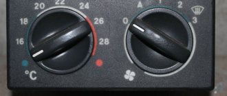
It is quite simple to understand that the interior heating system of the VAZ-2107 does not work. To do this, you just need to start the car and turn the interior heater switch. If sounds characteristic of a working stove fan do not appear, then it is necessary to look for the cause of the problem and fix it. If the heating system does not function in any mode, then most often the cause is a blown heater fuse.
Burnout of a protective device is the most common failure, which can be eliminated by replacing the failed product. Replacing it is very easy. The VAZ-2107 is equipped with new-style flag fuses.
Diagram of a new type of fuse box installed on a VAZ-2107 car
The block of protective devices is located under the hood on the right side in the direction of travel of the car, and is located on the partition between the engine compartment and the passenger compartment. To get to the block, you need to open the hood. The plastic cover of the block will open to view, on which there are symbols and names of parts. The heating system is responsible for the product marked F7 in the relay system R1. If this element fails, the cigarette lighter and glove compartment lighting will not work in parallel.
To replace, you must purchase a new thirty-amp fuse.
When purchasing a product, be sure to pay attention to its load. Do not install overrated products
This can be fraught with serious consequences, including a car fire.
First you need to dismantle the burnt element using tweezers, which are located in the block. Next, the new part is installed on the standard seat; to fix the contacts, you need to press lightly on the product.
At this point the work can be considered completed. If the protective element fails after prolonged use, the car heater will continue to operate without problems.
However, situations often occur when immediately after replacing a part, it burns out again. The fact is that the fuse is installed on the car in order to protect the electrical circuits of the car from overheating and burnout under heavy loads. A repeatedly failed element may indicate more serious problems in the electrical heating circuit of the machine.
Generator malfunction
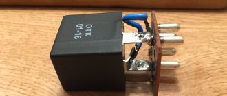
Glow plug relay
A car generator can throw up surprises from time to time. Unfortunately, brush wear is not the only reason why the charge check light may be on.
Possible malfunctions:
- damage to the regulator relay;
- problems with the diode bridge;
- broken stator winding.
Determining that something is wrong with a generator is quite simple. For this you will need a multimeter. In this case, you can immediately determine how charged the battery is. If the readings on a switched off engine are 12.6-12.7V, this indicates a full charge. 12.2-12.4 – charging about 50%. Less than 11.7 – the battery is completely discharged.
Ways to check the generator:
- when the engine is started, the voltage at the battery contacts should be about 14.7V. If it is very different, there is a problem with the generator;
- If you remove the terminal from the battery while the engine is running, it should continue to work. Otherwise, there is a malfunction with the generator;
- When the car is running, there is a clearly noticeable lack of energy.
To accurately diagnose and cure generator malfunctions, you need to have at least minimal knowledge of electrical engineering. If they are not there, it makes sense for you to seek advice from a specialist - you will definitely save time.
Firstly, periodically charge the battery, and secondly, monitor its external condition. And don’t forget to carry a spare alternator belt and brushes with you.
That's all, I hope the article was useful.
When problems arise with charging, many people ask the question: “why is the laptop connected but not charging?” and are in a hurry to replace it with a new one. Yes, the battery is a consumable item. It is designed for a limited number of charge/discharge cycles, and over time the capacity becomes significantly less than the nominal capacity indicated by the manufacturer. However, it is not necessary that the charging problem will be solved by replacement.
. In this article, we will look at three of the most common problems and tell you what to do to solve them.
Solenoid relay design
Hyundai Accent Fuses
To understand how to identify a malfunction, you first need to understand the design and operating principle of the retractor relay, as well as the starter relay, since they are located in the same housing.
So, there is a housing, inside of which two coils are installed - retracting and holding.
On the one hand, the body is covered with an ebonite or plastic cover. Three terminals for connecting wiring are installed on the outside of this cover.
One of the terminals is intended for connecting the “positive” wire from the battery, the second is for supplying electricity to the starter motor, and the third is for connecting the relay to the ignition switch.
On the inside of the cover there are two contact plates of the “positive” terminals.
Schematic diagram.
Inside the housing with the coils there is an armature, spring-loaded on one side, and a starter relay rod.
On the outside of the armature there is an eyelet, with which it engages with the Bendix fork and gear.