The VAZ-2112 car was produced at AvtoVAZ from 1998 to 2009, in Ukraine from 2009 to 2014. The following are color wiring diagrams (injector and carburetor) with a description of all elements for various modifications. The information is intended for self-repair of cars. Electrical circuits are divided into several blocks for ease of viewing via a computer or smartphone; there are also circuits in the form of a single picture with a description of the elements - for printing on a printer in one sheet.
To diagnose and repair yourself, first look to see if everything is okay with the generator. Is it put on well and does not sag? This procedure must be done with all versions of the fuel system, both carburetor and injection. We check the fuses according to the electrical diagram. The reverse side of the safety block cover will also be of great help. There are clues there that the diagram will help you decipher. Replace the burnt out element and try to start the car again. You need to check whether the battery terminals are tightly connected and whether they are oxidized. Is the wire going from the battery to the generator and to the starter damaged?
Modifications of the VAZ-2112 car
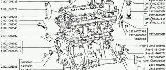
VAZ-21120 . Modification with a 16-valve injection engine with a volume of 1.5 liters and a power of 93 horsepower. 14-inch wheels were installed on the car. This modification has a problem with valves bending when the timing belt breaks. The problem can be solved by increasing the depth of the grooves in the piston bottoms.
VAZ-21121 . The car was equipped with a VAZ-21114 8-valve injection engine with a volume of 1.6 liters and a power of 81 horsepower.
VAZ-21122 . Budget modification with an 8-valve injection engine VAZ-2111. The car was produced without electric windows, the wheels were 13 inches in size, and the brakes were unventilated from a VAZ-2108 car.
VAZ-21123 Coupe . Three-door, five-seater hatchback. The only two doors for entering the car are 200 millimeters wider than those of the five-door hatchback, and they are mounted on new, durable hinges. The rear arches of the car have become wider. The engine was installed with a 16-valve injection engine with a volume of 1.6 liters and a power of 90 horsepower. The car was produced from 2002 to 2006 in small quantities, the reason for this was the high cost of the car.
VAZ-21124 . Modification with a 16-valve injection engine VAZ-21124 with a volume of 1.6 liters. Produced from 2004 to 2008. For this type of engine, the problem with valve bending was solved. To do this, the depth of the grooves in the piston heads was increased (up to 6.5 mm). In addition, the design of the cylinder block was changed to achieve a working volume of 1.6 liters, for which its height was increased by 2.3 mm, and the radius of the crankshaft was increased by 2.3 mm accordingly. There were also a number of other minor changes.
VAZ-21128 . The luxury version of the car, produced by Super-auto JSC, was equipped with a 16-valve VAZ-21128 engine with a volume of 1.8 liters and a power of 105 horsepower.
VAZ-2112-37 . A racing modification of the VAZ-2112, prepared for the “ring” in the Lada Cup qualifying group. The car was equipped with a 1.5-liter VAZ-2112 engine with a power of 100 horsepower. The racing car was equipped with a safety cage, an external aerodynamic kit and a front extension of the strut support cups.
VAZ-2112-90 Tarzan .
All-wheel drive modification with a VAZ-2112 body on a frame chassis with transmission and suspension parts from a VAZ-21213 Niva. It was also equipped with a 1.7 or 1.8 liter engine from the Niva.
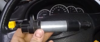
Checking the fuel pump relay yourself
At the beginning of the test, you need to get to the following elements: the pump fuse and its relay. Having decided which relay is responsible for the fuel pump, you should also inspect the fuse. Additionally, you need to check the fuse because the fuel pump relay heats up and then does not respond in a timely manner or does not operate at all due to a malfunction of the specified fuse.
Now let's look at another available way to check using the example of a VAZ 2110 car. The fuel pump relay itself in this model is located near the fuse.
To check, you will need a multimeter or a test light of no more than 0.25 A. Next, you should alternately measure the voltage at the control terminals of the device, simultaneously fixing the contact to ground
This method allows you to accurately determine whether the fuel pump relay needs to be replaced. If the warning light does not light up, the pump fuse is working or replaced with a known working one, then attention should be paid to the wiring from the relay to the computer. At the same time, the possibility of malfunctions in the engine control unit should not be ruled out.
Finally, we add that the element may also refuse to work or stick after failures or unqualified installation of a car alarm/immobilizer. The fact is that security and anti-theft systems with an engine start blocking function are often based on interrupting the power supply to the fuel pump. In this case, these systems must be diagnosed separately.
How to determine why the fuel pump does not pump or works poorly. Fuel rail pressure, pump diagnostics. Wiring, relays, fuel pump fuses.
Purpose, design features, installation location of the fuel pressure regulator of an injection engine. Signs of RTD malfunctions, checking the device.
Why does the starter turn normally, but the engine does not catch and does not start? Main causes of malfunction, checking fuel supply and ignition systems. Adviсe.
How to remove the engine start lock. Checking for random activation of the immobilizer and how to disable it. Diagnosis of possible alarm malfunctions.
The causes of whistling and increased noise during operation of the fuel pump are overheating of the pump. How to diagnose and fix the problem yourself. Tips and tricks.
Mechanical and electric fuel pump, design and principle of operation of the device, types of pumps and main malfunctions, operating features
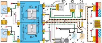
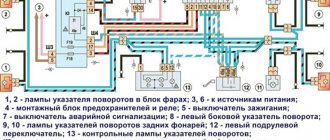
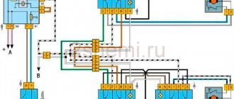
Electrical diagram of VAZ-2112
Designations: 1 – Headlight, 2 – Klaxon, 3 – Main radiator fan, 4 – Starter, 5 – Battery, 6 – Generator 2112, 7 – Gearbox limit switch (reverse), 8 – Actuator in the front passenger door, 9 – Power window enable relay, 10 – Starter relay, 11 – Heater fan, 12 – Electric heater partition drive, 13 – Main pump, 14 – Washer reservoir sensor, 15 – Driver’s door actuator, 16 – Front passenger window selector, 17 – Unlock button fifth door, 18 – Heater fan resistance unit, 19 – Main wiper motor, 20 – Driver’s window lift selector, 21 – Front passenger’s window lift motor, 22 – Central locking, 23 – Exterior light switch, 24 – Brake fluid leakage sensor, 25 – Pump additional, 26 – Driver's window lift motor, 27 – PTF on indicator, 28 – PTF switch, 29 – Dashboard, 30 – Heated glass on indicator, 31 – Heated glass switch, 32 – Steering column selector switch, 33 – PTF relay, 34 – Ignition switch, 35 – Main fuse block, 36 – Illumination of heater controls, 37 – Hazard warning button, 38 – Heater control controller, 39 – Glove compartment lighting, 40 – Glove compartment lid end cap, 41 – Cigarette lighter, 42 – BSK – display unit, 43 – Ashtray illumination, 44 – 12V socket, 45 – Instrument lighting switch, 46 – Actuator in the right rear door, 47 – Right rear passenger window selector, 48 – Clock, 49 – Right rear passenger window motor, 50 – Brake limit switch (closed – pedal is pressed), 51 – Left rear passenger window motor, 52 – Left rear passenger window selector, 53 – Actuator in the left rear door, 54 – Turn signal, 55 – Handbrake limit switch (closed – handbrake on), 56 – Rear wiper motor , 57 – Navigator's lamp, 58 – Interior lamp, 59 – Temperature sensor in the heater, 60 – Limit switch for the open front door, 61 – Limit switch for the open rear door, 62 – Trunk light, 63 – Rear optics (on the body), 64 – Rear optics (on the fifth door), 65 – License plate illumination.
The letters indicate the terminals to which it is connected: A – Front speaker on the right, B – Radio, C – Injector harness, D – ESD diagnostic connector, D – Front left speaker, E – Diagnostic connector for the heater controller, G – Rear right speaker, W – Rear left speaker, I – BC connector, K – glass heater thread, L – fifth door actuator, M – Additional brake light.
Wiring diagram VAZ-2112 injector 16 valves - full view
VAZ-21124 engine control circuit
Connection diagram of the VAZ-21124 engine control system with distributed fuel injection to Euro-2 emission standards (controller M7.9.7): 1 - ignition coils; 2 — nozzles; 3 - controller; 4 - main relay; 5 - fuse connected to the main relay; 6 — cooling system electric fan relay; 7 - fuse connected to the cooling system electric fan relay; 8 - electric fuel pump relay; 9 - fuse connected to the electric fuel pump relay; 10 — mass flow and air temperature sensor; 11 — throttle position sensor; 12 — coolant temperature sensor; 13 — solenoid valve for purge of the adsorber; 14 — oxygen sensor; 15 — knock sensor; 16 — crankshaft position sensor; 17 — idle speed regulator; 18 — immobilizer control unit; 19 — immobilizer status indicator; 20 - phase sensor; 21 — vehicle speed sensor; 22 — electric fuel pump module with fuel level sensor; 23 — oil pressure warning lamp sensor; 24 — coolant temperature indicator sensor; A - block connected to the wiring harness of the ABS cabin group; B — diagnostic block; B - block connected to the air conditioner wiring harness; G - to the “+” terminal of the battery; D — to the side door wiring harness block; E - block connected to the instrument panel wiring harness; G1, G2 - grounding points; I - the order of conditional numbering of plugs in the block of the immobilizer control unit; II - the order of conditional numbering of contacts in the diagnostic block.
Useful: VAZ 2110 diagram
Connection diagram of the VAZ-21124 engine control system with distributed fuel injection under Euro-3 toxicity standards (controller M7.9.7): 1 - ignition coils; 2 — nozzles; 3 - controller; 4 - main relay; 5 - fuse connected to the main relay; 6 — cooling system electric fan relay; 7 - fuse connected to the cooling system electric fan relay; 8 - electric fuel pump relay; 9 - fuse connected to the electric fuel pump relay; 10 — mass flow and air temperature sensor; 11 — rough road sensor; 12 — throttle position sensor; 13 — coolant temperature sensor; 14 — idle speed regulator; 15 — control oxygen sensor; 16 — diagnostic oxygen sensor; 17 — solenoid valve for purge of the adsorber; 18 — knock sensor; 19 — crankshaft position sensor; 20 — immobilizer control unit; 21 — immobilizer status indicator; 22 - phase sensor; 23 — vehicle speed sensor; 24 — electric fuel pump module with fuel level sensor; 25 — oil pressure warning lamp sensor; 26 — coolant temperature indicator sensor; A - block connected to the wiring harness of the ABS cabin group; B — diagnostic block; B - block connected to the air conditioner wiring harness; G - to the “+” terminal of the battery; D — to the side door wiring harness block; E - block connected to the instrument panel wiring harness; G1, G2 - grounding points; I - the order of conditional numbering of plugs in the block of the immobilizer control unit; II - the order of conditional numbering of contacts in the diagnostic block.
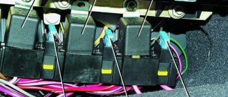
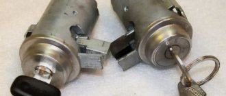
Where is the main relay of the VAZ 2110
Unlike most other relays, the main one is located not in the main one, but in an additional mounting block. The latter is in the cabin, but on the right side of the dashboard, and its cover is secured with 2 screws. This block has 6 elements, 3 of which are fuses and 3 are relays.
| Circuit breakers | Which electrical circuit are they responsible for? |
| 1 | Ignition module |
| 2 | Canister purge valve. Speed sensor. Heating sensor. Air flow sensor |
| 3 | Fuel pump and its relay. Injectors. |
Additional relays include:
| Relay | Purpose |
| 4 | Electric fan |
| 5 | Gasoline pump |
| 6 | Main ignition relay |
VAZ-2112 harness diagrams
Instrument panel harness diagram
1, 2, 3, 4 – instrument panel harness pads to the front harness; 5 — block of the instrument panel harness to the side door harness; 6, 7, 8 — instrument panel harness pads to the rear harness; 9 – rear window heating switch; 10 – light signaling switch; 11 – windshield wiper switch; 12 – block of the instrument panel harness to the radio; 13 – mounting block; 14 — instrument cluster; 15 – heater control controller; 16 – heater motor switch; 17 — block of the instrument panel harness to the ignition system harness; 18, 19 — blocks of the instrument panel harness to the air supply box harness; 20 — ignition switch; 21 – fog lamp relay; 22 – sound signal relay; 23 — power window relay; 24 — starter relay; 25 – seat heating relay; 26 – external lighting switch; 27 – fog lamp switch; 28 – cigarette lighter; 29 – lampshade lighting of the glove box; 30 – glove box lighting switch; 31 – switch for rear fog lights; 32 – right steering column switch; 33 – socket for connecting a portable lamp; 34 — instrument lighting switch; 35 – brake signal switch; 36 – sound signal switch; 37 – alarm switch; 38 – air distribution drive gearmotor; 39 – VAZ-2112 illuminator; 40 — instrument panel harness block to the front harness; 41 – trunk lock drive switch; 42 – rear fog light relay.
A – grounding point of the instrument panel harness.
Front 2112 harness diagram
Air supply box wiring diagram
VAZ-2112 heater harness diagram
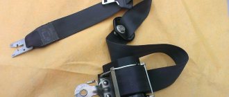
Side door harness diagram
Luxury side door harness diagram
Rear Harness Diagram 2112
- common terminal block of the wiring harness for connecting the wiring coming from the instrument panel (in the diagram under No. 1);
- terminal block of the wiring harness for connection with the wiring of the instrument panel of cars in the “standard” configuration and for connection to the side door harness for cars in the “luxury” configuration (in diagram No. 2);
- rear harness terminal block for connection to the instrument panel harness (No. 3);
- two 4-pin terminal blocks (for modifications 2112-3724558-10 16 valves). Indicated on the diagram as No. 4 and No. 5;
- side direction indicators (no. 6 – left, no. 7 – right);
- power supply to the individual lighting lamp (number 8 on the diagram);
- power supply for the general interior lighting lamp (No. 9);
- handbrake sensor connector (No. 11);
- rear lights (in the diagram No. 11 is left, No. 12 is right);
- interior temperature sensor connector (No. 13 in the diagram);
- connector for connecting 4 interior dome light switches (in the diagram under numbers 14,15,16 and 17);
- connector for trunk light (No. 18);
- reserve block of the wiring harness (in diagram No. 19). Can be used as a connector to connect to the side door wiring harness;
- block for connecting the wiring harness of the license plate lights (no. 20 in the diagram);
- The wiring grounding points are indicated in the diagram as A and A1.
For the lights, tailgate and license plate lights. They are connected together and the light harness is connected to the instrument panel harness and any side door harness, from it to any additional harness (will be below) with the trunk release button. The connector with the gray wire of the light harness is connected to the instrument panel; on luxury versions, it is connected to the instrument panel through the luxury side door harness (heated mirrors are connected to it).
Replacing the cigarette lighter
Replacement is carried out according to the following algorithm:
- Disconnect the wire from the battery terminal;
- Then the lining should be removed;
- Get the cartridge;
We pass the blocks with wires through the floor lining
Squeeze the lamp screen so that the legs come out of the light guide
Pushing the nest out of the cladding
We take out the socket and thread the blocks with wires
We adjust the contacts if the cigarette lighter does not return to its original position within the required time
Squeeze the latches and remove the light guide from the cladding
When reinstalling, the protrusion of the light guide should fit into the slot in the cladding
Repairing the cigarette lighter will not take you much time.
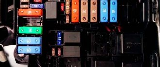
VAZ2112 fuses and relays
- F1 5 License plate lamps. Instrument lighting lamps. Side light indicator lamp. Trunk light. Left side marker lamps
- F2 7.5 Left headlight (low beam)
- F3 10 Left headlight (high beam)
- F4 10 Right fog lamp
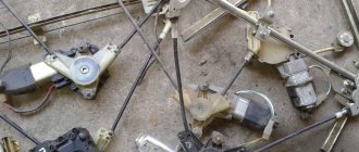
- F5 30 Electric door window motors
- F6 15 Portable lamp
- F7 20 Electric motor of the engine cooling system fan. Sound signal
- F8 20 Rear window heating element. Relay (contacts) for turning on the heated rear window
- F9 20 Recirculation valve. Windshield and headlight cleaners and washers. Relay (coil) for turning on the rear window heating
- F10 20 Reserve
- F11 5 Right side marker lamps
- F12 7.5 Right headlight (low beam)
- F13 10 Right headlight (high beam). High beam warning lamp
- F14 10 Left fog lamp
- F15 20 Electric seat heating. Trunk lock lock
- F16 10 Relay-breaker for direction indicators and hazard warning lights (in emergency mode). Hazard warning lamp
- F17 7.5 Interior lighting lamp. Individual backlight lamp. Ignition switch illumination lamp. Brake light bulbs. Clock (or trip computer)
- F18 25 Glove box lighting lamp. Heater controller. Cigarette lighter
- F19 10 Door locking. Relay for monitoring the health of brake light lamps and side lights. Direction indicators with warning lamps. Reversing lamps. Generator excitation winding. On-board control system display unit. Instrument cluster. Clock (or trip computer)
- F20 7.5 Rear fog lamps VAZ-2112.
- K1 – lamp health monitoring relay;
- K2 – windshield wiper relay;
- K3 – relay-interrupter for direction indicators and hazard warning lights;
- K4 – headlight low beam relay;
- K5 – headlight high beam relay;
- K6 – additional relay;
- K7 – relay for turning on the heated rear window;
- K8 – backup car relay.
Diagnostics
If it is impossible to start the car, when the starter turns the flywheel perfectly and there is a spark, you should check the fuel supply. If the pump works and gasoline enters the ramp, then the cause should be looked for further. To initially check the operation of the pump, just open the tank lid and, turning on the ignition, listen, the characteristic pumping noise should sound.
You should not immediately change the unit; first you need to check the fuse responsible for the operation of the electric motor of the fuel pump. Even if it is working properly, you need to check the power supply with a multimeter or probe and examine the relay. If power is supplied, then replacing the pump cannot be avoided.
It is more difficult when the pump is running, that is, it buzzes when turned on. First you need to check the condition of the filter, clean it if it is clogged with foreign impurities. Interruptions in operation can also be caused by faulty spark plugs, injectors, sensors, or a decrease in pressure in the fuel line. The pressure in the ramp, in turn, depends on the tightness of the main pipeline connections and the serviceability of the bypass valve.
It would be a good idea to measure the pressure using a pressure gauge with the fuel pump on but the engine stopped. Absence or significant deviation from the norm will indicate a malfunction.
Main settings
The fuse box is located under the decorative panel to the left of the steering column. Removing it is quite simple: press the latch and lower the structure down. Once you have access to the fuses, they can be removed and checked for integrity using a millimeter. The block contains only 20 fuses, designed for different current strengths.
Just look at the color of the fuse to determine what amperage it is designed for:
- tan runs at 5 amps;
- darker brown – at 7.5;
- red – at current strength 10;
- saturated blue – at 15;
- bright yellow is for 20;
- colorless or transparent – by 25;
- green – by 30.
Remember that you cannot install a stronger fuse element, and you should also not swap fuses. If the current strength is not observed, the protected unit may fail. If you do not have the necessary knowledge, entrust work with the electrical part of the board to a professional. To protect yourself from a car fire, do not install a wire in place of a failed fuse, as this will lead to a short circuit.
Behind the main unit you can notice separately connected devices, one of them protects the fog lights, and the second protects the central locking. Older cars do not have additional fuses protecting the car radio and alarm system.
If you equip your car with additional equipment, be sure to include these items.
Changes in switching and layout of mounting blocks
As we have already said, at various times the plant modernized the vehicle’s electrical equipment system and, naturally, made changes to the layout of the mounting blocks.
So, in the first ten years of production, the fog light fuse was located immediately behind the main unit, without any board, it simply hung on the wiring harness. Later it was moved first to a separate board on the left side of the center console, and then to the main mounting block.
As a result, the layout of the block has changed. The mounting block for 7 relays has catalog number 2110-3722010-08 , the block for 6 relays is marked 2110-3722010, and the newest block received the article number 2110-3722010-01 . In addition, there are blocks without legs for the relay for switching on the front optics K1 ( 2110-3722010-12 ), there is a block with legs, but without a relay (the legs are connected by jumpers and in order to install the head light relay yourself, the jumpers need to be cut), but mostly you come across blocks with legs for relays without jumpers. They involve either installing relay K1 or removable jumpers.
What fuses are included in the block?
In total, the block contains 20 elements. The number scheme looks like this:
- F1 protects the power circuit of the license plate lighting lamps, instruments, trunk and left side dimensions, as well as the control light indicating the operation of the side dimensions;
- F2 is responsible for the low beam of the left headlights;
- F3 – for high beam headlights on the left side;
- F4 works in conjunction with the right fog lamp;
- F5 protects electric window motors from overload;
- F6 is in the portable lamp circuit;
- F7 is responsible for protecting the horn and the cooling system fan of the power unit;
- F8 – for relay contacts and elements of the rear window heating system;
- F9 – for the relay coil for turning on the heated rear window, recirculation valve, windshield and headlight washers, as well as for their cleaners;
- F10 is in reserve;
- F11 protects the chain of dimensions located on the right;
- F12 is responsible for the functionality of the low beam of the right headlights;
- F13 – for the functionality of the high beam headlights on the right and the indicator light notifying that this type of lighting is turned on;
- F14 is in the circuit with the left fog lamp;
- F15 protects the luggage compartment lock and heated seats;
- F16 works with hazard warning lamps and turn signal breaker relay;
- F17 is responsible for the brake light and interior lighting lamps located near the clock or on-board computer screen, at the ignition switch, in the individual lighting circuit and on the ceiling;
- F18 – for glove compartment lighting, cigarette lighter and heater controller;
- F19 - for the control relay of the stop signal and side lights, locking, turn indicator lamps, on-board control system indication, clock or computer, generator winding and instrument cluster.
- F20 – for rear fog lights.
The rated current is determined by the color of the fuse. As you can see, most elements are part of a chain of several nodes.
Reasons for premature failure of fuses
- A natural factor is the duration of operation without intermediate prevention;
- Ingress of moisture, formation of condensation, oxidation of terminals, drying out of the insulating layer, open circuit of the electrical supply;
- Mechanical damage, accident, impact, collision;
- Damage to the car fender, windshield, which contributed to damage to the mounting block;
- Short circuit in the electrical supply circuit;
- Exposure to ultraviolet rays.
If after replacing the modules the equipment does not work, then the power supply circuit line is most likely damaged. In the worst case scenario, part failure. Carefully inspect the wiring sections from the battery, generator, starter to the relay switch.
The operating instructions for the technical means indicate the interval before replacing the modules of the mounting block is 40,000 km. In practice, the resource is 5 – 7 thousand km longer.
To prevent premature wear of modules, systematically check the condition of the wiring insulation, the quality of fixation of the terminals, and remove oxidation with fine sandpaper.
As consumables, purchase original domestically produced parts. Check the catalog numbers with the data specified in the instruction manual. Imported analogues are comparable in quality to the Russian manufacturer, but the price is twice as expensive
Electromagnetic relays
To relieve the car switch contacts from high current consumption, electromagnetic relays are used in the electrical circuit. There are 8 of them in total:
- K1 is responsible for the serviceability of the lamps;
- for turning on the front window wiper - K2;
- for turn signals and hazard warning lights – K3;
- for low beam headlights - K4;
- for turning on the high beam - K5;
- for heating the rear window - K7;
- for fog lights located at the rear - K8.
The block contains relay K6, which is additional. Before installing a new element into the system, check the wiring for short circuits, otherwise the parting that is protected by the fuse element or the fuse itself may fail. The described block is the main one, but the only one in the VAZ-2112 electrical circuit.
Sources
- ladaautos.ru/vaz-2112/raspinovka-bloka-predoxranitelej-vaz-2112-inzhektor-16-klapanov.html
- 2shemi.ru/shema-vaz-2112/
- vazdriver.ru/blok_predohraniteley_vaz2110/shema_i_raspolozhenie_predohraniteley_vaz_2110_2111_2112.html
- drive2.ru/l/2251582/
What do fuses do?
A fuse in any electrical circuit is necessary to resist a short circuit. It is able to open the circuit, but its fuse-link is destroyed by the heating temperature and such a fuse is not suitable for use. In the electrical circuit of the VAZ 2110 there are a lot of electrical circuits, which are divided into groups in accordance with the workload. Each group of circuits has its own rated operating current, when exceeded, the fuse is destroyed and forcibly opens the circuit.
Also, all circuits in the electrical circuit of the VAZ 2110 are conventionally divided into main and auxiliary. The main, constantly operating, regardless of the number of switched on devices, include only a few:
- ignition system circuit;
- power system circuit;
- sound signal;
- side lights, high and low beam headlights;
- stop signal.
In practice, all these circuits are constantly under load and, given their vital importance, they are also divided into smaller circuits, for which each individual fuse is responsible