Auto manufacturers today use many technological solutions to ensure more comfortable driving. One of such devices is CBKE. What is the central unit of body electronics Kalina 2 needed for, what functions does it perform and what malfunctions are typical for it - read in this article.
Description of CBKE
Unlike the first Kalin models, the second versions and Luxury equipment use an electrical package control unit instead of traditional relays to control the electronics. This device combines many functions, we suggest you familiarize yourself with them in more detail.
Connection diagram of elements and outputs of the CBEK
Functions
The electrical package control unit is designed to perform the following functions:
- Alarm. If the car's anti-theft system detects a break-in attempt, thanks to the CBKE, it will transmit information about this to the car owner's control panel.
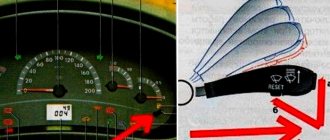
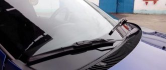
- Windshield wiper system control. Moreover, we are talking about both manual and automatic control (if the car is equipped with an electrical package control unit marked 21900-3840080-20).
- The device performs the function of controlling the windshield and rear window heating systems. This unit also controls the heating elements of the side rear-view mirrors.
- The electrical control unit also monitors the performance of the optics, both in manual and automatic control modes. In particular, we are talking about low-beam headlamps, side lights, and DRLs.
- Separately, we should highlight the function of ensuring the functionality of the high-range lighting.
- Turning lights, as well as light signaling.
- Vehicle interior lighting.
- The device monitors the performance and energy saving of devices belonging to the category of internal lighting of the car.
- Monitoring the state of the central lock, as well as performing the functions of locking and unlocking the locks themselves from the key, from buttons installed in the car interior, as well as in the doors.
- Another option is to open the luggage compartment lid using a button installed in the cabin.
- An equally important function is the control of electric drives, in particular, we are talking about power windows, as well as side rear-view mirrors.
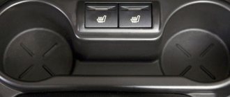
- Heating system for driver and passenger seats.
- Luggage compartment lighting unit (video author - Vladimir Kostyuchenkov).
Typical faults
If the electrical package control unit fails for some reason, this can lead to the following problems:
- Failure to operate power windows. Of course, before disassembling the control module, you should make sure that the window regulators do not work precisely because of it. It would be logical to first check the safety element, as well as the lift control unit, which is built into the driver's door. In practice, it often happens that the cause of power window failure is poor wiring contact on the unit itself.
- The optics stopped working - low beam, turn signals, etc. In this case, the safety elements, light sources and steering switch are first checked. There is a possibility that the reason lies in a broken contact directly on the switch; if this is the case, then they should be re-soldered. If the reason is that the unit is not working, it will need to be dismantled and disassembled in order to find the burnt-out element and re-solder it. If soldering does not help solve the problem, the device will have to be replaced.
- Some of the equipment has stopped working, while the devices, as at first glance may seem, are in no way connected with each other. The fact is that the module itself includes many elements and controllers, each of them is responsible for performing certain functions. If two or more controllers fail at once, it can cause serious damage. For example, the optics, heated rear and front windows, the trunk door and the window regulator will immediately refuse to work. It is necessary to locate the failed controller and replace it by re-soldering.
- A fairly common problem that can occur is a break in the wiring of the unit. It is installed in a virtually inaccessible place, but if electrical work is being done, for example, installing an anti-theft system, then most likely the car owner will encounter a TsBKE. And if the wiring is damaged during the work, of course, this will affect the functioning of the device and, accordingly, the performance of certain functions.
- Oxidation of contacts on module connectors. If you encounter such a problem, we recommend paying attention to the humidity in the cabin. Often, oxidation at the outlets occurs precisely as a result of high humidity. The contacts can be cleaned, this is not a problem, but the problem of humidity must be addressed, since otherwise it can lead to failure of the microcircuit as a whole.
- Board failure. The most terrible problem for the car owner, because because of this the device simply will not be able to work normally. Accordingly, it will need to be replaced, and this, in turn, costs a lot of money (author - Alexander Fisher).
Non-specific types of services
Even if the rules for safe operation of the vehicle are observed, the heater control unit may require servicing or replacement. This happens as a result of sudden switching of the heating knob of the Lada Kalina car. The operating instructions indicate that you must wait until the system warms up to a minimum, otherwise expensive repairs will be required.
From a financial point of view, the stove control unit will not be cheap, so its careful operation will save the family budget.
The heater control unit cannot be replaced independently due to the need to use special equipment. Much less often problems arise at the level of the engine control system.
The need to visit a service station will be caused by driving on a gravel road, an accident, or the result of unprofessional maintenance. The engine management system is responsible for fuel injection, so any deviations in its operation immediately put the car on hold. How long it will take to replace the engine control unit will be decided by the technician after an inspection.
It is cheaper, but repairs take much longer when the body electronics unit comes under attack. The problem can only be diagnosed in a service center. The duration is due to the fact that if the engine control unit can be replaced as a single whole, then part of the wiring must be changed along with the electronics.
Voltage surges or a simple short circuit can damage a certain sector. The light control unit will be the first to tell you about this.
Incorrectly working turn signals or emergency lights are the first sign indicating a failure in the electronic component of the car. There is no point in delaying a visit to the service center. Otherwise, the ESP unit responsible for dynamic stabilization will come under attack. Even with minor problems, the driver will notice a decrease in the lateral dynamics of the vehicle.
Lada Kalina requires regular maintenance as prescribed by the manufacturer. If the specified deadlines are met, each element of the system will work properly.
Replacement features
Briefly about the procedure for replacing the control module on Kalina 2:
- First, the instruments are dismantled from the center console; there is nothing difficult about it.
- Then the lower part of the center console trim is unscrewed, the trim is removed, and you gain access to the fuse and relay box.
- The mounting block with safety devices can be unscrewed, but it cannot be removed because it is connected by wires. You can rotate it a little so that it takes a horizontal position.
- You can stick your hand into the gap formed as a result of turning. Having done this, you will be able to feel the shelf on which the TsBKE is installed. A little to the left there is a bolt with which this module is fixed - you need to unscrew it.
- After this, through the top, through the instrument panel, you will need to disconnect the two connected connectors. After completing these steps, you can carefully dismantle the CBKE and remove it by slightly moving the fuse box. Please note that you should not pull the device too hard, since there are two more connectors on the other side that will need to be disconnected. When the wires are disconnected, the CBKE can be completely dismantled and repaired or replaced.
Photo gallery “Assistance in replacing CBKE”
Price issue
The cost of CBKE will vary depending on the modification. On average, such devices cost from 4,500 to 6,000 rubles.
Replacing the comfort unit on Kalina
#1 Student
- Users
- 22 messages
- City: Volgograd
- Gender: Man
Hello, dear forum users. I read and read the instructions, but “I look in the book and it’s clear what I see.” In general, I need help. Question 1. When replacing a block, what actions are needed? IMMO is not active in the engine ECU. The power windows do not work either every once in a while or spontaneously; when the ignition is turned on, the driver's window goes down.
2. If you buy a new key fob, you need to bind it (register it) to the comfort unit. The old key fob doesn’t even blink the LED. The battery is new.
Of course, the first thing I'll check is the wiring from the block in the driver's door to the block under the rear seat.
I’ve never encountered this, please treat it with leniency because... I’m just getting into it. But I will endure kicks in the right direction. Thank you.
Yes, I forgot to clarify, there is no training key.
Post edited by Student: 02 June 2015 — 13:36
#2 Vavan
Work is our life.
- City: Stavropol
- Gender: Man
1. New keychains always need to be “tied”!
2. check the block in the driver's door!
3. replacement of the comfort block!
#3 Student
- City: Volgograd
- Gender: Man
The block in the driver's door is new, I bought it yesterday. The comfort unit is still in question; we need to sort out the wiring. But the key fob is a problem, there is no training one. There is another type that works, but it’s just a blank without a transponder. As an option, what AVA suggested in a similar topic “The easiest way, since you do not have a training key, is to transfer the PCF microcircuit from the old to the new.” But the old one does not breathe, maybe this microcircuit is dead. In general, it’s still a dead end for me.
And according to the manuals that I dug up, the binding is only possible in the combination Keychain-APS-Comfort Block-training. But how do comfort units work with physically detached APS, or is this only possible when everything is already registered, and a separate key fob cannot be paired with comfort?
#4 krav
- City: Nikolaevsk, Volgograd region.
- Gender: Man
Let's start with the question, fellow countryman, do you have experience working with ECUs and what equipment do you have for the chip? and then we'll see.
#5 Student
- City: Volgograd
- Gender: Man
Yes, I have some experience. I sewed almost all ECUs of our brands except ME17.9.7, the module is expensive for me, there is an official Combiloader, nothing else yet, but sorry, external TLE
#6 krav
- City: Nikolaevsk, Volgograd region.
- Gender: Man
Well, that's good. As an option, you buy a new key fob, clean the Eprom in the ECU, seal new Eproms (or clean the old ones) into the APS and Norma. I won’t say for sure whether it’s necessary to do this, maybe someone will clarify, the dumps can be taken here https://www.chiptuner. content/immobil, you take a training key from a good friend, tie it (with a jack) with electrical tape to your key (a blank without a chip), carry out activation, train the key fob. Clean the Eprom ECU again. You have a working key fob and a working key without a chip. But! we have twin cars, or to avoid this, we’ll have to buy a lock with keys (I don’t know if they come separately) all subsequent steps are clear. Here’s another hint https://yadi.sk/d/KxDIGxYCh3PcY Learn to use the search for information that’s not secret, everything is in the public domain .
#7 Vavan
Work is our life.
- City: Stavropol
- Gender: Man
There is no need to solder new or clean microcircuits into APS and Norma. Yes, and from personal experience: Car key fobs trained with the same training key do not open each other.
#8 Harry
- City: Adygeisk
- Gender: Man
But! We have twin cars, or to avoid this, we’ll have to buy a lock with keys (I don’t know if they come separately), all subsequent steps are clear.
There will be no twins! And the “red” key from the previous car will come untied, so you’ll do a dirty trick on the friend from whom you took the key!
#9 Edua d76
- City Ufa
- Gender: Man
Why on earth would this come off? everything will work)))
Post edited by Edua d76: 03 June 2015 — 05:09
#10 Student
- City: Volgograd
- Gender: Man
Dear Gurus, thank you for the tips, they were presented right on a silver platter. I understand that you only need to prepare the injection system ECU, and the rest of the units will be retrained, i.e. there is no need to change anything. It’s probably better to buy a training manual anyway.
#11 rovbok
- City: Smolensk
- Gender: Man
You need a clean ECM unit (make it clean and trained). Need a NEW remote control, Need a red key. Working car system.
You teach if you have everything.
The Norma block or other blocks are retrainable. If you change the driver's door module, the system also needs to be retrained. If a red one learns with a different system, then he has unlearned the old one forever. In theory, PDU and Red are a couple that cannot be separated.
Post edited by rovbok: 03 June 2015 — 09:00
#12 Harry
- City: Adygeisk
- Gender: Man
Why on earth would this come off? everything will work)))
Have you tried checking?
#13 Student
- City: Volgograd
- Gender: Man
Yes, I don’t have enough theory. Honestly, I don’t understand how he will get rid of the previous car, will the code in the transponder change when learning another one? I always thought that you can train as many cars as you want with just red, but I see opinions are divided. I’ll speculate a little, well, I took a red one from a friend, trained the car I needed. Let’s say he got rid of the friend’s car, but he didn’t stop being a trainer, again we retrain the friend’s car with it and everything works again for him and he has a training key. Is that right? it won’t be for a friend, as Harry warned in post 8?
#14 Vavan
Work is our life.
- City: Stavropol
- Gender: Man
Everything is correct!! The maximum is to retrain again (from a friend) and that’s it!!
Video “Independent repair of the control module”
How to properly dismantle the CBKE and how to subsequently repair it - detailed instructions describing all the nuances are presented in the video below (author - MultiAlexander9).
The electrical circuits of modern LADA cars are very different from previous AvtoVAZ models. Some of the relays have disappeared and instead they are replaced by an electrical package control unit (comfort unit), which is responsible for the operation of the ESP, central locking, turn relays, turn signals, etc.). Lada Vesta and XRAY use a similar TsBKE module (central body electronics unit).
Possible breakdowns of body electronics and their elimination
CBKE allows you to free the driver from routine work and focus his attention on driving and managing the traffic situation. Despite this undeniable advantage, persistent failures of some nodes often occur. One of the most common malfunctions is the failure of turn signals and hazard warning lights. This most often manifests itself in the fact that the lamps simply burn continuously on the left side of the car. Before you begin repairing the TsBKE, you need to make sure that the lights are not burnt out, their contacts are not oxidized, the emergency stop button is working, and the wires are not charred.
The reason for the failure of the power windows may be a breakdown of the electronic control unit. There are other options: problems with the window regulator built into the driver's door, poor wire contact, incorrect installation of limiters.
You can repair the electronic unit yourself. To do this, you need to remove it from its regular place, open the cover and carefully inspect the circuit for the presence of soot or melted parts of the controllers. If you find obvious defects in the controllers, you should replace them and reinstall the software through a special connector on the electronic unit. In order to correctly replace burnt-out components, you need to have a “pinout” - information about connectors, wiring, input and output ports, various adapters and plugs.
Purpose and description
The central body electronics unit (CBEC) came from Renault and is located under the panel behind the glove box. The block is designed to perform the following functions:
- Access control system functions;
- Starter control;
- Control of relays of additional consumers;
- Control of the rear window heater and electric side mirror heaters;
- Windshield defroster control;
- Control of direction indicator and hazard warning lamps;
- Interior lighting control;
- Control of door sill lamps (for the “Lux” package);
- Trunk lighting control;
- Windshield wiper control (for “Classic” and “Comfort” trim levels);
- Energy saving control of vehicle interior lighting devices;
- Monitoring the state of the brake signal switch (BST);
- Monitoring the state of the clutch pedal position signal switch (CPPS) (for configurations with a manual transmission);
- Indication.
Basket
Double-glazed window control unit “Norma” 1118 – 6512010 for VAZ 11183 “Kalina”
©Aktuator On cars of the Kalina family, 2 types of non-interchangeable (by wiring) glass control controller 1118 - 6512010 and 11180 - 3763040 can be installed. 1118 – 6512010 has one 25-pin connection connector, 1118 – 3763040 (1118 – 3763040 – 10) – two connectors.
Read also: Pinout of radio connector for BMW E39
Remote control system for double-glazed windows “norm” on a VAZ 11183, Kalina. Controls power windows and central door locking. When the connector is removed, the engine does not start; the device performs some of the anti-theft functions.
Connection
| № | Wire color | Purpose, addressing |
| 1 |
* A regular shock sensor from any alarm system (Alligator, Saturn, Clifford, APS) is suitable.
+ 12 V connect to pin 12; body – on the 6th; We connect the signal wire (a ground appears on it at the moment of activity) to the 1st contact.
During normal arming, Kalina now reacts to an impact on the body (it sounds a horn and blinks turn signals). Similarly, instead of a shock sensor, you can connect a volume sensor (for example, single-level MMS‑1).
You can also connect a pager: + 12 V of the pager transmitter on pin 12, minus on pin 21.
Double-glazed window control unit 1118 – 3763040 (- 10 ) for VAZ 11183 “Kalina”
| External shock or volume sensor input (Not used)* | ||
| 2 | Pink/Black | To the door lock switch in the switch block |
| 3 | Brown/Green | K-Line. To Kl. 71 ECM, Cl. 18 APS‑6 |
| 4 | Brown | Connects to ground when the driver's door is closed |
| 5 | Grey | To rear window heating element |
| 6 | Black | Weight |
| 7 | Pink/White | To the door lock switch in the switch block |
| 8 | Yellow/Blue | In the instrument cluster, to the APS-6 indicator |
| 9 | Black/White | Connects to ground when opening the hood. C VK engine compartment lamp |
| 10 | Two White/Red | Connects to ground when opening the rear doors |
| 11 | Brown/Red | Connects to ground when opening the right front door |
| 12 | Output 12 V power supply for external sensor (Not used)* | |
| 13 | Not used | |
| 14 | Yellow | Pulse + 12 V, closing all doors and trunk |
| 15 | Red/Blue | To class 14 APS‑6 |
| 16 | Blue with Black | To the left direction indicator |
| 17 | Red/Blue | Impulse + 12 V, opening passenger doors |
| 18 | Red/Black | Pulse + 12 V, driver's door opening |
| 19 | Pink/Red | Impulse + 12 V, opening the trunk lock |
| 20 | Yellow/Blue | To terminal “15”, through fuse F 9, in the mounting block |
| 21 | Grey/Black | "-" Horn relay |
| 22 | White/Blue | Connects to ground when the driver's door is opened |
| 23 | Red | To permanent plus through fuse F 5, in the mounting block |
| 24 | Blue | To the right turn signal |
| 25 | White black | Connects to ground when opening the trunk |
| Controller board | ||
| Controller board |
Sign
| Possible reasons | Elimination method |
| The key code is not readable |
1 . 1 Malfunction in the VZ communication coil circuit
1 . 2 Malfunction in the circuit from the block to the communication coil to the APS ECU
1 . 3 Transponder missing in OK
1 . 4 The transponder in OK is faulty (detected during pre-production preparation)
1 . 5 The transponder in the Republic of Kazakhstan is faulty (detected during pre-production preparation)
1 . 6 Malfunction of the input transponder circuit in the APS ECU
1 . 8 The communication coil came off from the VZ pad on the inside
Read also: Installing methane gas system on diesel
2. 2 Malfunction of W‑Line circuits in the APS or ICS units
2. 3 Lack of supply voltage on the APS or KSUD unit
2. 4 The “Normal” electrical package is faulty (the control driver has burned out)
2. 5 KSUD does not contact
| 1 . 1 - replacement 1118 – 6105006 (set) - rearrange the transponder - rearrange the remote control 1. 2 - replacing the instrument panel harness 1. 3 -replacement of KSUD -replacement of 1118 – 6105006 (set) -replacement of remote control -train the system 1. 4 - rearrange the transponder (if there is a clean one) otherwise: - replace 1118 – 6105006 (set) - retrain the system 1. 5 - replace the remote control - train the system 1. 6 - replace the faulty unit - train the system 1. 7 - replace the remote control with a “clean” one - train the system 1. 8 - replace 1118 – 6105006 (set) - rearrange the transponder - rearrange the remote control | ||||
| 2. 1 W‑Line communication line break | 2. 1 - restore the circuit between unit No. 18 of the APS ECU and unit No. 71 of the KSUD 2. 2 - replace the faulty unit - train the system 2. 3 - eliminate the cause 2. 4 - replace the electrical package - retrain the system 2. 5 - eliminate the leak - replace the control valve - retrain the system | |||
| The read key code is not in the APS memory | 3. 1 - retrain the system 3. 2 - replace the KSUD - replace 1118 – 6105006 (set) - replace the remote control - train the system | |||
| The read key code is not in memory | Revealed during pre-production preparation | 4 beeps IC flashes | The KSUD was previously trained with a different system | — train the system |
| The system is not trained | Security function with remote control on/off, but the internal combustion engine can be started with any mechanical sting (the immobilization function does not work) |
|
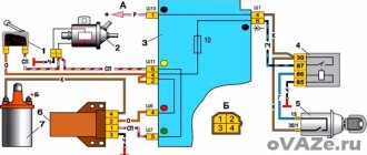
CBKE schemes
Electrical connection diagram for TsBKE on LADA VESTA: 2 – rechargeable battery; 3 – starter; 4 – rear left outer lamp; 5 – left headlight; 7 – rear window heating relay (K3); 8 – right headlight; 10 – rear outer right lamp; 13 – trunk light; 15 – fuse 60 A (F70); 16 – additional relay (K8); 17 – ignition switch; 26 – alarm switch; 30 – fuse 5 A (F20); 32 – left steering column switch (light alarm switch); 34 – fuse 60 A (F75); 35 – rear window heater; 44 – windshield heating relay 1 (K21); 46 – windshield heater; 47 – lampshade lighting of the glove box; 48 – switch for the glove compartment lamp; 51 – TsBKE (VSM controller); 58 – fuse 30 A (F61); 59 – left threshold lamp (installed on luxury equipment); 60 – right threshold lighting lamp (installed on the “luxury” configuration); 61 – relay of additional consumers (K2); 63 – fuse 10 A (F32); 84 – fuse 3 A (F43); 87 – left outside mirror; 88 – right outside mirror; 120 – additional starter relay (K23); 134 – brake signal switch; 138 – fuse 5 A (F15); 164 – air conditioner control panel (connection diagram for the “comfort” package); 185 – interior lighting unit with ERA-GLONASS interface module; 196 – fuse 5 A (F24); 200 – fuse 15 A (F11); 201 – fuse 15 A (F12); 202 – fuse 10 A (F13); 203 – fuse 10 A (F14); 204 – fuse 5 A (F17); 205 – fuse 5 A (F16); 229 – fuse 3 A (F49); 230 – clutch pedal position signal switch; 231 – windshield heating relay 2 (K22); 233 – fuse 5 A (F80)
- location of fuses F1-F59 and relays K1-K20 in the interior mounting block;
- location of fuses F60-F80 and relays K21-K28 in the motor mounting block
Ignition system diagram Lada Kalina Lux
1 – oil pressure warning lamp sensor; 2 – coolant temperature indicator sensor; 3 – additional fuse block; 4 – fuses for the electric fan of the engine cooling system; 5 – electric fuel pump relay; 6 – relay for the electric fan of the engine cooling system; 7 – ignition relay; 8 – relay 2 of the electric fan of the engine cooling system; 9 – relay 3 of the electric fan of the engine cooling system; 10 – electric fan of the engine cooling system; 11 – throttle position sensor; 12 – idle speed regulator; 13 – coolant temperature sensor; 14 – diagnostic block; 15 – ignition system harness block to the instrument panel harness block; 16 – solenoid valve for purge of the adsorber; 17 – speed sensor; 18 – ignition system harness block to instrument panel harness block 2; 19 – mass air flow sensor; 20 – crankshaft position sensor; 21 – oxygen sensor; 22 – controller; 23 – rough road sensor; 24 – diagnostic oxygen sensor; 25 – ignition coil harness block to the ignition system harness block; 26 – ignition coils: 27 – ignition system harness block to the ignition coil harness block; 28 – spark plugs; 29 – nozzles; 30 – resistor; 31 – air conditioning system pressure sensor; 32 – blocks of the ignition system harness and injector wiring harness; 33 – phase sensor; 34 – knock sensor.
Ignition system wiring harness -11184-3724026-10. Ignition coil wiring harness -1118-3724148-00. Injector wiring harness -11184-3724036. A – to the “plus” terminal of the battery.
Tell me, where can I get the pinout for the connector of the control unit for the “Lux” electrical package? I wanted to install a pager and a sensor, I found everything, took it apart - and there were 2 connectors, 20 thin and a second connector, 10 thick. The third connector is not connected. THERE WAS a rumor that the block on the luxury ones was a Priorovsky one, but I also couldn’t find a description of it, and besides, it is combined there with the APS-6. There is no need to send it to the search, because... Finding anything on a new engine is almost unbelievably lucky
Well, no one installed an alarm on the luxury version? I downloaded the Priora diagram - the Priora unit has 20 contacts and 2 more connectors, everything seems to fit together, but the Priora for the additional sensor has a 3-pin connector, and mine has this connector with about 8-10 contacts. And there is still no description.
Connecting the signaling to the central locking system
Now we get to the most interesting part. The contacts of the signaling relay must be connected to the gap in the brown wire (see diagram in Chapter 1). Moreover, this will be required regardless of the configuration. Oddly enough, we won’t need power cables at all. And the task now looks like this: you need a two-wire signal cable connected to the break in the brown cord.
Preparing for connection, completion
The moral here is:
- If you were able to remove the central lock control unit, connect the cable to the break in the wire connected to pin “7” of the control unit;
- If you have removed the door trim, then pull the cable out of it (from the point where the brown cord breaks).
It is clear that the second side of the cable must reach the relay connector of your alarm.
Option for the “Lux” package
So, this means that there is a button on the armrest in the cabin that allows you to lock the locks. From one of the contacts of the button, to which a “plus” is applied when pressed, you need to stretch the cord to the signaling unit. Nothing else is required, and you can connect the alarm according to the following scheme:
Scheme for the “Lux” configuration
According to reviews, this option is suitable if we are talking specifically about the “luxury” configuration. By the way, the resistor can be connected to the gap in the wire designated “blue” (the common contacts are then connected with a jumper).
Each cord that is re-laid must not touch metal surfaces. Otherwise, in places of contact, the wire is protected with a tube that can withstand temperatures of 250 degrees. This is how you can protect yourself from unforeseen consequences.
Option for the “Norma” configuration
Let's say there is no button in the cabin that allows you to perform emergency closing. Then you need to connect the signaling to the central locking system according to the following scheme:
Scheme for the “Norma” configuration
As you can see, unlike the first option, there are no resistors here, and positive voltage is not used at all. But in the luxury configuration the effect that is characteristic of this scheme will not be observed:
- We perform closing from the key fob - all locks are locked;
- We try to open the locks with the key fob - only the driver's lock unlocks.
If you are satisfied with this property, try to implement the scheme in practice. And other options, more advanced, look much more complicated.
Read what is said about installation safety in the previous chapter. Do not neglect the advice about disconnecting the negative terminal. We work only with signal circuits, so nothing will fail even if connected incorrectly. However, be careful not to confuse the locking and unlocking relays, which are located in the alarm unit. This unit is usually equipped with a 6-pin connector (for details, see the signaling manufacturer's instructions).
How to remove CBKE? Repair of faulty CBKE
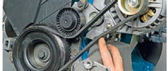
So, CBKE (eng. BCM - Body Control Module) - the Central Unit of Body Electronics is located in the car interior, on the left, above the fuse box.
You can view the pinout of the TsBKE, a description of its functions and the diagnosis of its malfunctions by following the link - TsBKE - Purpose, Functions, Diagnostics (*.pdf format, size
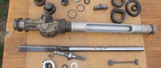
To dismantle it, according to AVTOVAZ technological instructions, it is necessary to remove the instrument panel. Not the instrument panel, with gauges and indicators, but the entire panel! Something like this.
26.1MB). Information on removing the CBKE is on page 281.
On our own behalf, we can add that it is difficult to remove the TsBKE without removing the instrument panel. And installing it back in its place, securing it as it should be, is even more difficult, but possible. The Internet is full of instructions, everyone can make it up, just like we can in our own way.
We had to remove the body electronics unit because the left turn light was constantly on. All paths and electrical circuits led there. There was no turn relay in this Lada Granta.
Block number 21900-3840080-20.
From the inside, the TsBKE board looks like this. Next to the large gray connector, the culprit of the constantly lit direction indicators is the BTS-5242-2L (power key).
You can get acquainted with the “datasheet” of this microcircuit by following the link: Datasheet BTS-5 242-2L (*.pdf format, size
In general, in terms of repairs, there are no tricks. Either we order and change the microcircuit, or we order and change the TsBKE.
Regarding replacing the block. According to the document “CBKE - Purpose, Functions, Diagnostics”, there is also a unit with number 21900-3840080-10 , but it does not control the electric drives of the side mirrors, does not have auto lights, does not control the rear windows and does not control the trunk lighting.
If you have any questions or clarifications to the article, you can always voice them in our WhatsApp, Viber or Telegram groups.
Our news
Attention! We moved. New address st. Vysotskogo, 33/3 (on the territory of the Research and Production Enterprise “Engineer”).
Our car service becomes the official Partner of ARS ADAKT LLC.
Our car service has been certified and received permission to install, repair and maintain WEBASTO heaters.
Jatco automatic transmission and long climb
The operating manual supplied with all VAZ cars with automatic transmission says the following: it is recommended to turn off overdrive when climbing. This is how you can prevent the box from moving to the last, fourth gear. Overdrive is turned off by a special button located on the selector housing (it is turned on by it). Look what we have on the selector: “D”, “2”, “1”. Well, between “D” and “2” there could be a number “3”, but they decided to implement this option using a button.
On a long climb, the automatic transmission should under no circumstances try to shift from third gear to fourth. Otherwise, although nothing terrible will happen, the box begins to operate in a mode that is unusual for it.
Since the control unit “doesn’t know” anything about the angle of the body, it means that the driver is required to turn off overdrive at the right time. Actually, foreign cars also have a similar option. And up to the third stage inclusive, if the car is moving no faster than 60-70 km/h, the engine speed will remain at an average level. That is, you won’t be able to spend a lot of fuel with overdrive turned off, unless, of course, you want to accelerate up to 70 km/h on a hill (prohibited in traffic regulations). The Jatco transmission settings were correctly selected from the very beginning of the release of the “second Kalina”.
Video about the entry of "Kalina-2" with automatic transmission onto a hill covered with ice
Two configurations and two schemes
In the “Norma” version, if it has a central locking system, you can use two control wires. Ground is supplied to one of them if the locks need to be opened, and to the second one if the locks need to be closed. The period of connection to ground should take 0.7 seconds, and most alarms have such a setting.
If we talk about the “Lux” configuration, the control wires will not help us here. The relay contacts built into the alarm will have to be connected to the breaks in the power cords. Despite all the complexity, there were no complaints about this scheme, and we will consider it right now.
The “luxury” option is the most complex
First you need to make sure that the central locking system in the car is really connected according to the “Lux” scheme. The control button located on the door must be trigger (non-latching). If you have exactly this type of car, you will have to tinker. It will be necessary to extend 4 power cables to the signaling unit. These cords, in turn, must go from the break point of the two standard wires (yellow-white and yellow-black). Find them in the bundle under the threshold.
Any alarm system is supplied with two relays, one of which is activated for closing, the second for unlocking the locks. Power cables drawn from the break points are connected to the relay contacts.
The part of the yellow-white wire that goes to the actuators is connected to the common contact. Another relay contact (normally closed) is connected to the second half of the cable. They connect to the yellow-black wire in a similar way, but here an opening relay is used, not a locking one. Each of the normally open contacts receives power.
Any power wiring is supplied with power through a fuse.
In our case, the rating “15 Amperes” is used. Immediately before installation, you need to call the pair of wires that are directed to the actuators. The probe should show a value of 1.2 - 1.3 Ohms. And of course, when performing installation work, you first need to remove the negative terminal from the battery. Be careful!
Connection option for “Norma”
Let's say there is a switch in the driver's door, but it has two fixed positions. Then it will be easy to connect the alarm. You will need to make not 4, but 2 taps, and not from the power cords, but from two signal cords. There is no need to make breaks, just make a T-shaped connection. The diagram here looks standard:
You can complete the installation without breaking the wires at all.
In the circuit discussed above, there is no fuse. We connected to the signal wiring, not the power wiring, and theoretically we can not be afraid of any short circuits. Still, it is better to insulate the free terminals on the signaling. The same applies to all connection points.