Important In the key fobs transmitters included in this kit…
Zx 750
- Image
- Text
1
Important
The key fobs transmitters included in the kit of this security system use
uses dynamic encoding of the transmitted control code package, which makes attempts to scan or memorize the code (code grabbing) for the purpose of its subsequent reproduction completely useless, since any subsequent control command of the transmitter key fobs changes every time the button is pressed. Therefore, when the hijacker reproduces the intercepted signal from your transmitter key fob, the security system simply will not respond to it.
To provide the highest level of protection for your vehicle, this
The security system has a function for manually arming or disabling the security mode. In some cases, for example, when the key fob transmitter for remote control of the system is lost or does not work, or perhaps your key fob transmitter is blocked by powerful radio emissions from a jammer or code-swapping interceptor, you may need to manually arm or manually disarm the system. Read the sections “Manually arming the system” and “Manually disabling the security system,” which detail the procedures for arming and disarming the system in such a situation.
To effectively combat interception systems with code substitution ALWAYS
try to turn on (turn off) the security mode from the transmitter key fob by bringing it as close as possible to the system antenna if previous attempts were unsuccessful. This will automatically make the previous code inoperative and eliminate the possibility of substitution. To increase the level of vehicle protection, also use the phased system shutdown mode.
If the F13 “Secret Code” function is programmed, then recording the codes
new key fobs, changing the secret code, changing the status of programmed functions from F12 to F20, emergency disarming of the system, turning off the system when triggered in the “Anti Hi Jack” modes are possible only after entering the secret code! Changing the parameters of functions F1 to F11 does not require entering a secret code and is always available.
Car security system with two-way communication, three service channels, interactive LCD pager, anti-theft and car hijacking protection systems.
Installation and Use Guide
ZX 750
How to install
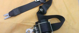
The installation documentation recommends securing the headunit housing inside the vehicle using 2 screws. It is prohibited to mount the unit in the engine compartment, since the casing does not protect the electronic components from moisture. It is not recommended to install the unit next to the car's standard controllers (due to the risk of electromagnetic interference). To mount the siren on the engine shield, a metal bracket is used, the bell is tilted down (to drain condensate).
The antenna unit is attached to the windshield using 2-sided tape. Since there is an LED on the unit, it is necessary to ensure visibility of the element from the driver’s seat and from the outside through the car window. An additional limit switch is installed on a metal body panel outside the water drainage area. It is recommended to place the element inside the protective contour formed by the rubber sealing edge. To reduce the risk of false alarms, it is necessary to adjust the switch stroke in the range of 6-8 mm.
Wiring connection
The manual for the 750 series signaling shows a diagram of connecting the main and auxiliary harnesses. The cables are equipped with multi-colored insulation, which simplifies the alarm connection procedure.
The equipment allows you to use a standard car horn instead of a siren (after installing an additional unloading relay).
The documentation provides recommendations for connecting the complex to cars from different manufacturers; the alarm design includes support for vacuum drives of the central locking system.
Contents Main functions of the Sheriff ZX system ...
Page 2
- Image
- Text
2
Table of contents
Basic functions of the Sheriff ZX 750 system. . . . . . . . . . . . . . . . . . . . . . . . . . . . . . . . . . . . . . . . . . . . . . . . . . .4
Controlling the operation of the Sheriff ZX 750 system
. . . . . . . . . . . . . . . . . . . . . . . . . . . . . . . . . . . . . . . . . . . . . . .6
Functions of transmitter key fob buttons. . . . . . . . . . . . . . . . . . . . . . . . . . . . . . . . . . . . . . . . . . . . . . . . . . . . . .6 Combinations of LCD indicators. . . . . . . . . . . . . . . . . . . . . . . . . . . . . . . . . . . . . . . . . . . . . . . . . . . . . . . . . . . . . . .7 Programming codes for new transmitters and anti-robbery transponders. . . . . . . . . . . . . .9 Commands for controlling the Sheriff ZX 750 system from the transmitter key fob. . . . . . . . . . . . . . . . . . . . . . . . . .11 Remote (two-way communication key fob) activation/deactivation of system functions. . . . . . .14 Confirmation signals of the two-way communication key fob of the Sheriff ZX 750 system. . . . . . . . . . . . . . . . .17 Operating modes of the security system LED indicator. . . . . . . . . . . . . . . . . . . . . . . . . . . . . . . . .20 Siren signals. . . . . . . . . . . . . . . . . . . . . . . . . . . . . . . . . . . . . . . . . . . . . . . . . . . . . . . . . . . . . . . . . . . . . . . . . . .20 Operating modes of vehicle side lights. . . . . . . . . . . . . . . . . . . . . . . . . . . . . . . . . . . . . . . . . . . . . . .20 Low battery indicator/battery replacement. . . . . . . . . . . . . . . . . . . . . . . . . . . . . . . . . . . . . . . . . .21
Additional commands for arming the system
. . . . . . . . . . . . . . . . . . . . . . . . . . . . . . .22
Passive (automatic) arming of the system. . . . . . . . . . . . . . . . . . . . . . . . . . . . . . . . . . .22 Manually arming the system. . . . . . . . . . . . . . . . . . . . . . . . . . . . . . . . . . . . . . . . . . . . . . . . . . . . . . .22 Arming with the engine running (“Any Stop”). . . . . . . . . . . . . . . . . . . . . . . . . . . . . . . . .23
Car protection in security mode
. . . . . . . . . . . . . . . . . . . . . . . . . . . . . . . . . . . . . . . . . . . . . . . . . . . .23
Protecting the car when the security mode is on. . . . . . . . . . . . . . . . . . . . . . . . . . . . . . . . . . . . . . . . .23 Warning signals about an attempt to break into a car. . . . . . . . . . . . . . . . . . . . . . . . . . . .24 Control of coded blocking relay R350 - function F20 (additional option). . . . . . . . . . .24
Disabling the system
. . . . . . . . . . . . . . . . . . . . . . . . . . . . . . . . . . . . . . . . . . . . . . . . . . . . . . . . . . . . . . . . . . . . .25
Valet button. . . . . . . . . . . . . . . . . . . . . . . . . . . . . . . . . . . . . . . . . . . . . . . . . . . . . . . . . . . . . . . . . . . . . . . . . . . . .25 Manual disabling of the security system using the “Valet” switch. . . . . . . . . . . . . . . . . . . . . .25 Disabling the system using a personal code. . . . . . . . . . . . . . . . . . . . . . . . . . . . . . . . . . . . . . . . .25 Service mode “Valet” (temporary shutdown of the system). . . . . . . . . . . . . . . . . . . . . . . . . . . . . . . . . .26
Additional security features
. . . . . . . . . . . . . . . . . . . . . . . . . . . . . . . . . . . . . . . . . . . . . . . . . . . . . . .26
Additional (emergency) call using the antenna module button. . . . . . . . . . . . . . . . . . . . . . . . . . . . . .26 Automatic safe locking of doors when the vehicle starts moving (function F10.2). . .26 Automatic safe locking of doors when pressing the “C top” pedal of the car (function F10.3). . . . . . . . . . . . . . . . . . . . . . . . . . . . . . . . . . . . . . . . . . . . . . . . . . . . . . . . . . . . . . . . . . . . . . . . . . . .26 Step-by-step sequential unlocking of the driver's then passenger doors (functions F18.1). . . . . . . . . . . . . . . . . . . . . . . . . . . . . . . . . . . . . . . . . . . . . . . . . . . . . . . . . . . . . . . . . . . . . . . . . . . .27 Automatic re-arming of the system (function F6). . . . . . . . . . . . . . . . . . . . . . . . . . . . .27 Disarming the system in two stages - AV function (function F14). . . . . . . . . . . . . . . . . . . . . . . . . . .27 Passive engine blocking (immobilizer function F15) . . . . . . . . . . . . . . . . . . . . . . . . . . . . . .27 “Anti Hi Jack” mode (protection against car theft and seizure). . . . . . . . . . . . . . . . . . . . . . . . . . . . . . . .28 Disabling the “Anti Hi Jack” mode. . . . . . . . . . . . . . . . . . . . . . . . . . . . . . . . . . . . . . . . . . . . . . . . . . . . . . . . .28
Functions
Functions supported by the security complex:
- active and passive activation of protection is provided;
- deactivation of security in 2 stages;
- additional immobilizer;
- it is possible to turn off the complex by entering a password;
- ensuring protection of a car with a running engine;
- calling the driver from inside the car;
- built-in unit for controlling the central locking;
- alarm memory;
- automatic engine start;
- searching for a car in the parking lot.
Advantages and disadvantages
Equipment advantages noted by owners in reviews of the 750 Pro:
- low cost;
- extended set of functions (including automatic engine start);
- range of the communicator;
- long battery life.
Disadvantages of the security complex:
- the control signal is intercepted and decrypted by special scanners;
- loss of communication between the remote control and the complex in the presence of interference;
- inconvenient setup and programming algorithm;
- The communicator screen is destroyed by impacts (for example, when the remote control falls to the ground).
Additional service functions for security system management…
Page 3
- Image
- Text
3
Additional service functions for security system management
. . . . . . . . . . . . . . . . . . .29
Remote control of the siren (on/off, night mode of the system). . . .29 Automatic door unlocking when the ignition is turned off (function F11). . . . . . . . . . . . . . . . .29 Remote control of additional devices (CH 2) . . . . . . . . . . . . . . . . . . . . . . . . . . .29 Turning on/off external devices (starting the engine) (function F19.3) . . . . . . . . . . . . . . .thirty
Security system programming
. . . . . . . . . . . . . . . . . . . . . . . . . . . . . . . . . . . . . . . . . . . . . . . . . . .31
Programming system functions. . . . . . . . . . . . . . . . . . . . . . . . . . . . . . . . . . . . . . . . . . . . . . . . . . . . . . . .31 Changing the personal system deactivation code. . . . . . . . . . . . . . . . . . . . . . . . . . . . . . . . . . . . . . . . .32 Table of programmable functions of the Sheriff ZX 750 system. . . . . . . . . . . . . . . . . . . . . . . . . . . . . . . . . .33 Brief description of system functions. . . . . . . . . . . . . . . . . . . . . . . . . . . . . . . . . . . . . . . . . . . . . . . . . . . . . . . . .35
System installation
. . . . . . . . . . . . . . . . . . . . . . . . . . . . . . . . . . . . . . . . . . . . . . . . . . . . . . . . . . . . . . . . . . . . . . .36
Appendix 1. Remote digital locking relay R350, R350NC. . . . . . . . . . . . . . . . . . . . . . . . . . .52
Additional functions
Page 5
- Image
- Text
Additional functions
•
“Save” mode—controls the power saving of the two-way communication key fob.
•
Remote control of the “Turbo timer” function (on/off).
•
Temporary blocking of LCD key fob buttons.
•
Remote activation/deactivation of the “Valet” service mode.
•
Search for a car in a parking lot.
•
Remote control of the siren channel in security mode (disable/enable - night mode).
•
Temporarily disabling the shock sensor when arming.
•
Silent communication control mode (manual mode), checking, updating the LCD screen status.
5
Key Features
Features specific to the Sheriff 750 anti-theft systems:
- The anti-theft system controls nine security zones, which provides a high level of vehicle protection. The microprocessor module is equipped with a function to bypass faulty zones. When arming, the alarm performs diagnostics to identify problematic elements.
- Possibility of passive activation of protective mode. When this function is enabled, sound and light pulses will not be triggered.
- Ability to remotely activate and disable Panic mode. When it is turned on, the optical instruments of the car, as well as the system siren, will emit alarm signals, which will scare away potential intruders from the car.
- Anti-grabber option. Will provide reliable protection of the car from theft and forceful seizure. The function is intelligent; if configured correctly, it will be able to detect a violent seizure of the car. The determination is made based on readings from motion sensors, the brake pedal and the parking lever. After turning on the function, after one minute or another time interval programmed by the user, the internal combustion engine will be blocked.
- Possibility of step-by-step deactivation of the protective mode. You can disable only the shock sensor, and then other elements.
- Option to search for a car in the parking lot. When activated, the car’s optical devices will blink a certain number of times, which will allow the consumer to find the car in a large parking lot.
- Turbo timer. Maintains operation of the power unit after remote start. Its presence prevents engine wear.
- Option to call the car owner from inside the car. By pressing a special button located on the transceiver, the driver will receive a call signal sent to the communicator.
- Possibility of organizing independent opening of the driver's and passenger's doors when the security is turned off.
- Availability of a passive immobilizer. The device is used to block the motor in case of an unauthorized start attempt.
- System alarm mode memory. If there is a power outage or the battery is disconnected, then after its activation the alarm will automatically switch to protection mode.
- Alarm alarm memory. The microprocessor unit is equipped with a memory module, which allows you to store information about all alarm activations in the absence of the owner. Using the communicator, the consumer will be able to find out which security zones were activated and what caused their activation.
- Availability of Slave mode. Its use provides the ability to control the power saving system of the main communicator with feedback. This will allow the car owner to change the batteries in the remote control less often.
- The communicator keys are locked. Will prevent accidental pressing of buttons when the pager is in the car owner's pocket.
- Possibility of temporarily deactivating the sensitivity controller when the protective mode is turned on.
- Ability to monitor the status of the R350 code module. This device is mounted optionally; the module is not included in the basic package.
- Comfort option. Its correct setting will ensure automatic raising of the windows, sunroof and folding of the side mirrors. These devices must be electrical to work with this option.
An overview of the configuration and capabilities of the Sheriff 750 alarm is given by the Arnage channel.
Controlling the operation of the sheriff zx 750 system
Page 6
- Image
- Text
Controlling the operation of the Sheriff ZX 750 system
Functions of transmitter key fob buttons
Functions of transmitter key fob buttons
Button for arming the system (ARM) Button for disarming the system (DISARM) Button for controlling the programmable channel CH2, controlling system modes when arming/disarming the system Button “ ” for remote selection of functions and changing system parameters
6
Rice. 1
Attention
In order to increase the battery life of the two-way communication key fob, the presence of communication between it and the central unit of the system is monitored manually. To check the presence of communication with the key fob pager and the system, issue a command by pressing any button except F. If the connection is present, the system will “return” confirmation of the command execution with a corresponding sound signal. Otherwise, after 3 seconds the LCD indicator
antenna will disappear from the screen and the buzzer will
will give one long and one short signal.
Indicator for turning on the power saving mode of the pager key fob...
Page 7
- Image
- Text
7
Indicator for turning on the power saving mode of the pager key fob. The mode is turned on/off in the “Disarmed” mode by simultaneously pressing buttons 1+F(5) until the “Save” indicator appears or disappears. In the “Disarmed” mode, the pager key fob turns off its receiver after 30 seconds, as evidenced by the disappearance of the antenna indicator.
Valet mode activation indicator
(service mode).
Always present on the display while the system is in “Valet” mode.
System sensor status indicator.
The shock sensor is turned off. Triggering in the main zone of the shock sensor is disabled; arming by bypassing a faulty shock sensor. Flashes when the sensor is triggered by a strong impact.
Indicator for turning on the vibrate ringer mode.
“AUTO” indicator—activation of passive arming.
Indicator for turning on door locking during passive or manual arming.
Indicator of the siren sound signal when the “Security” mode is activated.
Indicator of siren deactivation in “Security” mode.
Indicator of anti-burglary function operation. Flashes when the Anti Hi Jack anti-theft feature is activated.
Engine running mode indicator. Flashes in active mode.
Indicator for receiving a call signal from inside the car. Flashes when receiving a call from the pager.
Indicator of operation of temporary timers.
Flashes when the time is counting down in the operating turbo timer mode.
Battery charge indicator (battery is fully charged).
The indicator blinks - low battery charge (less than 30%).
Indicators of activity of additional channels. Shows the status of the CH2 channel line.
Ignition on indicator. Shows the status of the vehicle's ignition line.
LCD display indicator combinations
Communication indicator (antenna).
Disappears if there is no connection with the central unit or if a request is made to execute a non-existent command.
Indicator of the enabled “Turbo timer” mode. Indicates that the mode is activated in the system.
Rice. 2
Specifications
Description of the technical properties of the Sheriff 750 Pro security systems:
- Pulse data is transmitted via a 433 MHz radio frequency channel.
- The security system is powered from an electrical network designed for 9-15 volts. The best option would be to install alarms on passenger cars, minibuses and SUVs with a 12-volt network. But installation on motorcycle equipment is also possible.
- Pulse data transmission is performed using dynamic signal encoding. The CFM 2 code is used for encryption.
- The amount of current that the anti-theft complex consumes when the protection mode is activated is no more than 20 mA.
- The maximum operating radius of the communicator in signal reception mode will be up to 2 thousand meters. But this parameter depends on many factors, in particular, weather conditions, architectural features of the area, as well as interference.
- According to the manufacturer, the temperature range of the alarm is from -40 to +85 degrees.
- The operating range of the spare pager is up to 70 meters.
- The operating range of the main communicator with a display in command transmission mode is 900 meters.
Door status indicator: ...
Page 8
- Image
- Text
8
Door status indicator:
— on (doors locked)
with the ignition on or in “Valet” mode (service mode).
- off (doors unlocked)
us) with the ignition on or in the “Valet” mode (service mode).
System command execution indicator. The headlights are flashing.
Hood switch activation indicator. Flashes when the hood switch is triggered in the “Armed” mode or when arming with the hood open.
Door limit switch operation indicator. The door icon flashes when the system is triggered by the door limit switches or when arming bypassing faulty (unready) door limit switches.
Trunk limit switch activation indicator. Flashes when the trunk limit switch is activated in the “Security” mode or when arming with the trunk open.
Programming codes for new transmitters, Programming transmitters
Page 9
- Image
- Text
9
Programming codes for new transmitters
Important
Please note that when programming a new transmitter into the system memory, all previously programmed transmitter codes are erased, therefore, when programming additional transmitters, existing transmitters must be programmed again. The system maintains up to four key fob codes in memory, regardless of whether the codes are from four different key fobs or the same code is written into the system 4 times.
Transmitter programming
Recording codes for new transmitters (F13 - “Valet” state).
Important
Remember that each operation must be performed within 5 seconds after the previous operation. If the 5 second interval is exceeded, the system will automatically exit the programming mode, which will be confirmed by one short and one long beep from the siren. If the ignition was turned off during programming, the system will immediately exit the programming mode, confirming this with one short and one long siren signal.
•
Disarm the system, get into the car and turn on the ignition.
•
Press the Valet button switch 3 times. You will hear one short siren signal. Click the Valet button again. You will hear a long siren tone indicating that the system is ready to program new transmitters.
•
Press and hold button 1 (see Fig. 1) of the first transmitter until you hear a long siren signal, confirming that programming of the first transmitter is completed (the transmitter channels will be programmed automatically). At the same time, the LED will begin to flash rapidly.
•
Press and hold button 1 (see Fig. 1) of the second transmitter until you hear a long siren signal confirming that programming of the second transmitter is complete. The LED will begin to flash slowly.
•
Repeat step 3 for the remaining transmitters.
•
To exit transmitter programming mode:
a) turn off the ignition or b) wait 8 seconds without performing any actions.
You will hear one short and one long siren signal to confirm exit
transmitter programming, and the system LED will go out.
Recording codes for new transmitters (F13 - “Secret code” state)
Disarm the system using a key fob or by entering a secret code with the “Valet” button, i.e. •
Turn on, turn off and then turn on the ignition;
•
Using the “Valet” switch, enter the first digit of the code (the number of presses of the “Valet” button corresponds to one digit of the code);
•
Turn off and then turn on the ignition;
•
Using the “Valet” switch, enter the second digit of the code (the number of presses of the “Valet” button corresponds to the second digit of the code);
•
Turn off and then turn on the ignition. The system should confirm with an audible signal that the correct code has been entered;
User manual
Full use of all functions of the key fob is possible only after linking the communicator to the electronic module.
Designation of buttons and icons on the key fob
Location of buttons on the key fob
Purpose of the buttons
Key fob indicators
Description of indicators
Description of indicators
Description of indicators
Setting up the key fob
Programming a new remote control is done as follows:
- The car alarm protection mode is disabled. The driver gets into the car, installs the key in the lock and turns it to the ACC position to turn on the ignition.
- The Valet service button is clicked three times. The siren speaker should play a short pulse. The service button is pressed by the car owner again. The siren will play an extended beep, which indicates that it is ready to pair new communicators.
- The first key on the main remote control is pressed. It must be held in this position until the siren plays one long signal. When this happens, the binding of the first communicator is completed. The signal indicator LED will blink.
- To bind a second communicator, press its first key. It is held until the siren plays a long beep.
- The previous paragraph is repeated to link the remaining pagers.
- To leave the binding mode, you must turn off the ignition or do not perform any actions for eight seconds. To confirm exiting the settings menu, the siren will play first one short-term and then a long signal.
Between each action of setting up the Sheriff 750 car alarm key fob, the time interval should be no more than five seconds, otherwise the binding procedure will have to be repeated all over again.
To record a new secret password, do the following:
- Disable the security alarm mode. To do this, you can use your communicator or service button.
- The ignition system is turned on, deactivated and re-activated.
- Using the service key, the first digit of the password is entered. The button must be clicked as many times as it corresponds to the first digit of the code. If it is 4, then you need to click on Jack four times.
- The key in the lock is set to the Off position, and then again turned to ACC to turn on the ignition.
- Using the service key, the next digit of the secret password is entered. The number of clicks corresponds to the second number.
- Manipulations with turning off and activating the ignition are repeated. If the user entered the password correctly, the anti-theft complex will emit a sound signal.
- Then the Valet emergency button is pressed three times. The alarm siren will play one short pulse. After the beep, the button is clicked again. The siren speaker will play another long signal, this indicates that the electronic module is ready to bind other communicators.
- Now the pager binding procedure is performed in the same way as described above. First, press the first button of the main communicator until the sound signal is heard, and then the first key of the spare key fob. The operation is performed similarly for each pager. To exit the programming mode, the ignition is turned off or the consumer does not perform any actions for eight seconds.
User Kolya spoke about the features of linking new communicators to the Sheriff electronic alarm unit.
Setting up autorun
When using the function for the first time, you must properly prepare the car:
- The car stops; there is no need to turn off the engine.
- The driver pulls the parking brake lever.
- On the communicator, click the CH2 key twice. If the engine stops, the siren will play one signal and a flashing indicator will appear on the screen.
- The key is set to the Off position and removed from the lock. The driver leaves the car and locks the door locks by pressing the corresponding pager button. When pressed again, the power unit of the car stops. To make further starting of the internal combustion engine easier, it is recommended to set the heating device to the minimum temperature. This will reduce the engine warm-up time.
- To further start the motor, press the CH2 key at a distance. To use this feature, you can use either a primary or a backup communicator.
- If you need to turn off the motor, click the CH2 key twice again.
Setting up the motor to start at certain time intervals is done as follows:
- The F key on the communicator is clicked twice.
- The LED indicator on the device body will begin to blink.
- The F key is pressed again. The selected symbol will be displayed on the screen.
Alexander Yushko cited the features and spoke about the function of remote engine start in the Sheriff 750 alarm system.
By the blinking frequency of the diode light bulb, you can determine the operation of the previously configured cycle:
- If the diode does not blink, then the option to start the internal combustion engine by time interval is disabled.
- If the indicator blinks uniformly, the engine will start once per hour.
- When the diode blinks twice, and then there is a pause, then the engine start cycle is two hours.
- If the driver observes three flashes followed by a pause, the start time interval will be four hours.
- Four flickers and a pause indicate that the engine start time interval is set to 12 hours.
To activate this option, click the door lock key and use it to adjust the time interval parameter. To disable the function, press the door lock button. If the option is disabled, the LED indicator will stop blinking. When a function is selected, the F key is pressed to make it active.
Autorun malfunctions
Problems that may occur when setting up a function:
- The motor does not start when commanded or at a specific start time. The cause of the problem may be that the consumer has not met the requirements to start the internal combustion engine. When the car alarm tries to start, the lights will blink and the siren will play sound signals. An error indicating that there is a problem will be displayed in memory. The exact cause can be identified through diagnostics.
- The engine does not start or stops immediately after starting. The requirements for setting up the function are met, but the engine does not start or starts but shuts down within five minutes. When the anti-theft system tries to start the engine, there are four attempts. If after these attempts it is not possible to start the internal combustion engine, then a fault code will be stored in the memory of the electronic module. You can determine the breakdown in diagnostic mode by deciphering the combination.
- The engine does not start, and when you try to start the internal combustion engine, clicks are heard in the area of the dashboard. The reason may be due to incorrect installation of the anti-theft system. You need to make sure that all elements are installed correctly. If necessary, seek assistance from alarm installers.
- There is no option to enable the autorun option. The driver configures the key fob and activates the function, but it does not turn on. The reason may be errors made during installation, or that the consumer did not take into account all the conditions for remote start.
Press the push button switch...
Page 10
- Image
- Text
•
Press the Valet button switch 3 times. You will hear one short siren signal. Click the Valet button again. You will hear a long siren signal confirming that the system is ready to program new transmitters;
•
Press button 1 (see Fig. 1) of the first transmitter key fob. The system will confirm the recording of the new key fob code into memory with a sound signal;
•
Press button 1 (see Fig. 1) of the second transmitter key fob. The system will confirm the recording of the new key fob code into memory with a sound signal;
•
Repeat step 3 for the remaining transmitters;
•
To exit transmitter programming mode:
a) turn off the ignition or b) wait 8 seconds without performing any actions.
You will hear one short and one long beep from the siren to confirm that you have exited the mode.
transmitters and the system LED will go out.
10
Comments
Select → I found instructions for my car alarm here! #manualza
- Click →
The owner of Ikea sold his soul to the devil, but he could not assemble it according to the instructions.
Manualza!manualza.ru