Classification by operating principle
- Mechanical or electromechanical tachometers with direct drive. The revolutions are transmitted to the dial indicator through a flexible shaft, which, through a worm gear, receives rotation directly from the crankshaft or one of the transmission shafts. The operating principle of the indicator is based on the phenomenon of eddy current induction. The operation and design of a magnetic tachometer are extremely similar to the operating principle of a car speedometer. In modern cars, a similar tachometer design is not used.
- Electric machine. A distinctive feature is the connection to a generator. It is used primarily on diesel engines, but for the purpose of unification, a device of this type can also be used on gasoline engines.
- Electronic. The signal can be taken either from the ignition system or directly from the computer. Installed on gasoline and diesel internal combustion engines.
Design and principle of operation
Main components of electric machine and electronic tachometers:
- measuring unit, or signal converter. It can be based on elements of analog circuitry or built using special microcircuits;
- display unit with analogue or digital display of the number of revolutions;
- auxiliary elements.
The operation of electronic tachometers is based on the conversion of individual signals or pulses captured from the computer, ignition system or generator into a signal “understandable” for the display unit.
Connection diagram
When looking for the reason why the tachometer does not work, it is first of all important to understand the connection diagram and the type of signal. There are 3 typical connection schemes:
- to a contactless ignition system (the tachometer wire is connected to the primary circuit of the ignition coil). The operating principle is based on measuring the frequency of voltage surges in the primary circuit of the ignition system. Calculating the ignition angle is impossible without focusing on the number of crankshaft revolutions, therefore the sparking frequency directly depends on the crankshaft rotation speed. On 4-cylinder internal combustion engines, a full revolution of the crankshaft corresponds to 2 voltage pulses in the primary circuit. Accordingly, the higher the crankshaft rotation speed, the greater the frequency of voltage surges;
- connection to the contact ignition system. The operating principle and connection diagram are similar to the BSZ, but the design of the measuring unit will differ depending on the voltage of the input circuit;
- connection to the engine ECU. The principle of operation is still based on recording voltage pulses in the primary circuit of the ignition system, but the signal to the tachometer comes from the engine control unit;
- connection to the generator (the tachometer signal contact is connected to terminal W of the generator). The rotation of the generator pulley is carried out by a belt drive from the crankshaft, so the rotation speed of the generator rotor will always be proportional to the crankshaft speed. The change in the number of revolutions of the crankshaft can be calculated by constantly measuring the amount of EMF generated on the winding. According to its principle of operation, an electric machine tachometer resembles a regular one class=”aligncenter” width=”448″ height=”412″[/img]
If you broke down on the way
In recent years, the production of Lada Kalina cars (ECU) of domestic production was replaced with Korean ones.
The kind they put on Hyundai cars. After that, power steering failures became significantly less frequent. But they started installing Korean blocks on new cars. And how many thousands of Kalinas travel all over the roads, with old electronics? Our advice to you is, at the first opportunity, change the electronic control unit on your car to a modern one, you will be healthier.
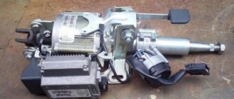
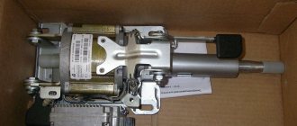
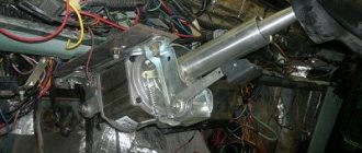
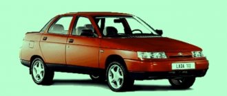
Electric power steering for modern cars has already become an integral part of them. On the Russian market it was first installed on the Lada Kalina (VAZ 1118). The electric booster added both a lot of positive emotions and a lot of negative ones. Failure of this unit occurs quite often on the first samples. Our guest today was no exception - a car of the Lada “Kalina” family (Fig. 1).
The situation is quite typical: the client complains that the electric power steering sometimes turns off and the electric power steering warning light comes on
This situation is very annoying, because not only the owner uses the car, but also his wife. It is much more problematic for a woman to turn the steering wheel without electric power assistance.
We start the car, and the electric power steering fault light actually lights up and it becomes quite difficult to turn the steering wheel. It is imperative to deal with this problem.
We connect the diagnostic scanner and connect to the EMUR control unit.
On the monitor screen we see the following error: C1044 - incorrect sequence of the rotor position sensor. What is a rotor position sensor and where is it located?
Let's take a break from our malfunction for a moment and touch on a little theory. Let's understand the EMUR device and what main parts it consists of. Let's consider all its parts separately.
Design EMUR Kalina 11186-3450008-00
- Steering shaft
- Electric motor
- Electronic control unit
- Torque sensor
- Rotor position sensor
We remove the EMUR. On the nameplate (Fig. 7) there is article number 11186-3450008-00 manufactured by Aviaagregat, Makhachkala.
Remove the steering wheel, steering column switches and ignition switch. To get to the torque sensor, you must first remove the electric motor. We unscrew the bracket with 4 bolts, the cardan shaft, the lock nut and the 3 bolts securing the electric motor.
This is what we got (Fig. 12)
Next we pull out the shaft.
We take out the torque sensor winding (Fig. 17), having previously unsoldered the wires from the board (Fig. 16).
Design of an inductive torque sensor.
The inductive sensor consists of two concentric cylinders with holes (perforation slots), which are fixed to the shaft and rotate with it. And two concentric coils with primary and secondary windings, fixedly inserted into the EMUR housing. We will not go into various terminology, but let’s put it simply: an alternating current with a frequency of 20 kHz is supplied to the primary winding, and if we apply force to the shaft (that is, we begin to rotate the steering wheel), then a voltage “ ” or “-” appears on the secondary winding depending on the direction of rotation, and the magnitude of this voltage is directly proportional to the applied torque (force). Thus, the electronic control unit (ECU) determines with what force you rotate the steering wheel in one direction or another.
So, we’ve dealt with the torque sensor, let’s move on to the next one, namely the rotor position sensor (Fig. 20), which is located on the back cover of the electric motor.
The EMUR of the Lada “Kalina” uses a 3-phase switched inductor (brushless) motor. In order for it to start rotating in one direction or another, the electronics must understand what position the rotor is currently in and, after determining the position, apply voltage to certain stator windings at the right moments. To determine the position, a rotor position sensor (RPS) is used.
Diagram and design of an optical rotor position sensor.
3 optocouplers located at an angle of 120 degrees - LED (LED a,b,c) and photodiode (PD a,b,c), correspond to the location of the motor stator windings phases A, B, C. A disk is installed on the motor rotor, and when it rotates Photodiode a, b or c is triggered. In this way, the electronics determines the current position of the rotor.
Next, let’s look at the electronic control unit EMUR (Fig. 23), we won’t say anything special about it, we’ll just look at the photo of the board itself.
Well, we’ve sorted out the EMUR device, let’s return to our malfunction, with which the owner of the Kalina car came to us. What needs to be done to make everything work as it should? A fairly common malfunction with this modification of the EMUR is poor soldering of the optocouplers on the rotor position sensor board. It is enough to simply solder all the contacts of the optocouplers (Fig. 24) to revive the EMUR, which we hastened to do.
After soldering the board, we assemble everything in the reverse order and start the car. Hurray. The EMUR fault light went out and the steering wheel began to rotate very easily.
New Lada: Spare parts catalog VAZ-2194 Kalina 2 - station wagon with prices
We have a scanner to check parameters and read fault codes, but what should a simple motorist who does not have this equipment do? How to count errors without a special scanner? It's quite simple.
In order to read the self-diagnosis codes of the Kalina EUR you need to:
1) With the ignition off, short the 6th contact of connector X2 of the EMUR control unit to ground, or short-circuit contacts 6 and 7 (Fig. 26). There is no 6th pin in connector X2, so we installed a piece of white wire there and connected it to the 7th pin (ground).
Let's look at the EMUR circuit for a more detailed understanding.
Tips for motorists
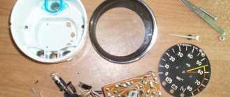
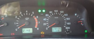
On the left side of the instrument cluster of the Lada Kalina passenger car, there is a tachometer, from which the driver can determine the engine speed. Malfunctions in the electrical circuit of this device can lead either to a complete cessation of its readings (the tachometer needle is at zero when the engine is running), or to jumps in the needle on the scale, which does not allow determining the exact number of crankshaft revolutions.
The first thing drivers do in this case is open the hood and remove the negative terminal of the battery for a couple of minutes, thus trying to clear errors from the controller’s memory. If this does not help restore the tachometer to working order, then it is necessary to conduct a diagnostic test to identify error numbers. To do this, use your finger to press the button, which resets the daily mileage in the instrument cluster odometer. And without releasing it, turn the key in the ignition switch to the “ignition on” position.
All instrument needles must begin to move from the zero position to the final position and back. If the tachometer needle does not start moving or starts moving but does not return to its original position, this will indicate that the malfunction is located inside the instrument cluster. Considering that the stepper motors, with the help of which the tachometer needle moves, and circuit boards are not available for retail sale, the entire instrument cluster assembly will have to be changed.
If the tachometer passes the test, then the fault will have to be looked for outside the instrument cluster. On their own, most drivers can only check the condition of the terminals in the tachometer electrical circuit blocks, since this can be done visually. First of all, you need to check terminal No. 30 of the low-voltage tachometer input, which should be connected to the brown-red wire coming from the electronic control unit (ECU). To do this, you will need to remove the instrument cluster by disconnecting the wiring harness block from it. Terminal No. 30 should not be bent or show signs of corrosion.
Why doesn't the tachometer work on the VAZ 21099?
Indications of various engine operating parameters displayed on the VAZ 21099 dashboard allow you to monitor its operation in various operating modes.
Incorrect operation or failure of one of these indicators deprives the driver of visual control over the key characteristics of the engine. Such a malfunction can subsequently cause serious damage to engine components and parts.
One of these devices is the tachometer. It is used to record the rotation speed of the crankshaft. What to do if the tachometer of the VAZ 21099 does not work?
Causes of malfunction
So, basically the malfunction appears due to disassembling the instrument cluster. On many forums, car owners complain that after disassembling the panel, this defect appeared.
But this may not be the only reason . Let's consider the main ones:
- The tachometer control motor burned out.
- The tachometer controller has failed.
- Error in the electronic control unit.
- Part of the instrument cluster board was burnt.
Thus, the main problems have been found.
Disassembling the dashboard
Treatment methods
In order for the tachometer needle to return to its place, it is necessary to eliminate the causes of this effect. So, let's look at how to treat various malfunctions with your own hands:
- The motor burned out. It is necessary to unscrew the panel and unsolder the element contacts. Check the resistance, which should be 300 ohms. If necessary, clean the contacts and solder the motor back. If this does not work and there is no resistance, then you need to install a new motor.
- Tachometer controller . If the motor is sealed and the tachometer does not return, then you need to find the control controller and check it. Replace if necessary.
Now we know how to eliminate the causes of the malfunction.
How can I lubricate and adjust the EUR?
How and with what to lubricate the amplifier?
Litol can be used as a lubricant; the procedure is performed as follows:
- First you need to remove the plastic casing; to do this, unscrew the bolts that secure it. To unscrew, use a Phillips head screwdriver. It is also advisable to remove the lower cross member of the instrument panel, located under the steering wheel.
- Next, unscrew the two bolts that secure the amplifier itself; for this you will need a 13mm wrench. After this, the column can be released down.
- Unscrew another bolt, after which you can do the actual lubrication.
- First, the steering wheel is turned to the left until it stops. The lubricant is poured into a 10 cc syringe, which needs to be sprayed into the hole formed. You need to throw out all 10 cubes.
- Then the steering wheel is turned to the right until it stops - the syringe is again directed into the hole, all the lubricant is sprayed out.
- After this, the steering wheel should be turned to the middle position and again sprinkled with lubricant into the hole.
- Next, the steering wheel must be turned in different directions until it stops several times. The lubrication operation is repeated again.
- Then all the components are assembled in reverse order.
Why does the tachometer needle jump and what should I do?
Every driver knows that there is a device called a tachometer on the dashboard of a car. However, the principle of its operation, what exactly it measures is not known to everyone. The tachometer is a very important device in a car. It shows the engine crankshaft speed, that is, it actually shows the efficiency of the car engine. But this is only one of the functions of this device. Based on its indicators (the tachometer needle jumps or displays incorrect results), one can draw conclusions about the presence of certain malfunctions in the car.