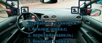
I installed mirrors from Priora with electric drive and heating. To control the mirrors, I took an ESP unit from a wedge with mirror adjustment using a central lock and two ESP buttons.
Pinout for connecting power window buttons. 1 to the motor wire in the driver's door 2 to the motor wire in the driver's door 3 ground (you can connect only one of them, they are combined with 5 pins inside) 4 to (+) for the driver's window (I combined it with 6 pins) 5 ground (if 3 pin is connected to ground, then this one does not have to be connected) 6 to (+) for the passenger window 7 missing 8 to the dimensions 9 to the 3rd leg of the button in the passenger door 10 to the 6th leg of the button in the passenger door
Pinout for central locking connection. 1 closing 2 ground 3 missing 4 dimensions 5 backlight ground 6 missing 7 opening
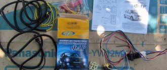
for installation you needed: - wire lugs, I don’t know how many - heat-shrink tube, bought 3 meters (a little left) - wire, bought 30 meters (about a meter and a half left)))
Window closer on Priora and operation of power windows without turning on the ignition
Have you ever been annoyed by the moment when you are late, turn off the ignition and when you are ready to run, you notice or remember about the open windows... You have to put the key back into the ignition and press the power window buttons. This is not so bad, but sometimes in your haste you simply forget about the open windows and leave the car to plow open. This happened to me a couple of times.
Remembering how convenient it was with power window closers on my previous car, I immediately included the installation of power window closers on the Priora in my plans.
The most interesting thing is that the Priors themselves have closers, especially on the luxury ones, where electric windows of the front and rear doors are installed, but the functionality of the closers is terrible. You can raise or lower the windows when arming or disarming by holding the buttons. The same functionality is available on foreign cars. On my car, you can only control the front windows this way; the rear windows are silent (the passport says that this is optional). But it’s still long and inconvenient, and besides, it works as desired. I wanted all the windows to lift on their own when arming, and also for the power windows to work without the ignition. The solution was found on the website www.masterpriora.ru
Closer MASTER v1.20
The MASTER window closer is designed for automatic closing of windows when arming vehicles of the LADA PRIORA family. The closer is a device consisting of a board with electronic components connected by wires with connectors for connection to the standard electrical wiring of the car. To protect against damage, the board is enclosed in a heat-shrinkable shell. This device is not included in the List of goods subject to mandatory certification; it is regulated by the Decree of the Government of the Russian Federation “On approval of the list of goods subject to mandatory certification and the list of works and services subject to mandatory certification” dated August 13, 1997 N 1013 (as amended from April 29, 2002, dated February 10, 2004 N 72).
Functions: Adjustment of glass when arming with standard alarm system. When you press the lock button on the radio remote control, the normal mode of raising the windows is activated; you do not need to hold the button. Adjusting the windows when arming with an additional alarm.* When arming with an additional alarm, the windows are raised.** Control of the windows from the driver's door module within 30 minutes after turning off the ignition.* If the security mode is not turned on, then it remains possible to control the electric windows within 30 minutes from the moment the ignition is turned off using the keys of the driver's door module. Control of the front windows from the driver's door module "with one touch". If you briefly press the up/down button, the glass will automatically go up/down all the way. You can stop the glass at any time by pressing the up or down key again. If you hold the key longer, the glass will move while the key is held. Additional output for the “armed/disarmed” status of the standard alarm. Used to turn off/sleep devices when armed with a standard alarm system, such as a car radio. When using an additional alarm, after disarming, 12 V will appear at the output after opening the driver's door. Additional output for sound signal. When arming with the lights on, the output short-circuits to ground twice (a beep will sound twice). The output is connected to the gray-blue wire of relay K9 (standard alarm horn relay) in the relay and fuse block. Input for disabling glass finishing. Used to disable glass finishing when arming, for example in winter. Does not affect other functions."Turn signal extension." Short-term (not fixed) activation of the direction indicators turns on the corresponding indicator 3 times.
The pleasure costs only 700 rubles, and its installation does not require removing the door trim, and if you use only the first function, the entire installation will take no more than 5 minutes and you will not need to cut the standard wiring.
1. Unscrew the two screws on the driver’s door sill trim.
Master class on installing door closers
- First, remove 2 nuts on the door trim near the driver.
- Then we lift the plastic clips and free the car threshold from the lining.
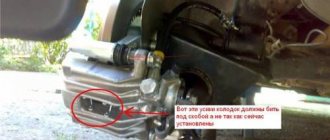
- Carefully remove the noise and temperature insulating materials and get to the power window connector shown in the figure. Be sure to ensure that all openings in the car, on the side of the body, are closed.
- Next, you need to disconnect the existing connector and install the connector of our new device.
This is all that needs to be done to install the power window closer on the Lada Priora. Now you don’t have to worry that when you turn off the ignition in your car, the window glass will remain down. The closer will do his job.
And that is not all! If you want to leave the car ventilated while closing it, the power window closer function can be disabled.
I installed mirrors from Priora with electric drive and heating. To control the mirrors, I took an ESP unit from a wedge with mirror adjustment using a central lock and two ESP buttons.
Pinout for connecting power window buttons. 1 to the motor wire in the driver's door 2 to the motor wire in the driver's door 3 ground (you can connect only one of them, they are combined with 5 pins inside) 4 to (+) for the driver's window (I combined it with 6 pins) 5 ground (if 3 pin is connected to ground, then this one does not have to be connected) 6 to (+) for the passenger window 7 missing 8 to the dimensions 9 to the 3rd leg of the button in the passenger door 10 to the 6th leg of the button in the passenger door
Pinout for central locking connection. 1 closing 2 ground 3 missing 4 dimensions 5 backlight ground 6 missing 7 opening
VAZ 2170 | Power windows
Power windows
The operating mode of the power windows is determined not only by the switches, but also by the power window control unit on the support with additional relays on the left under the dashboard.
Operation: When the ignition is on, the window in the driver's or passenger's door next to the driver slides up or down until it stops by briefly pressing or releasing the switch. In this case, the movement of the glass stops if you briefly press the key in the opposite direction.
For safety reasons, this convenient method of activation in the rear doors only exists for lowering the windows.
When the ignition is turned off, when you press the button, all windows move all the way down only. The glass only moves up when the power window button is pressed.
Child protection: The electric windows in the rear doors are locked by a central switch in the driver's door armrest.
Anti-theft device: If the driver's door is opened and closed again while the engine is off, all power windows are disabled.
Convenient closing: In all vehicles with power windows, they can be closed simultaneously when the driver's door and the passenger door next to the driver are closed. To do this, you need to hold the key in the “closed” position a little longer. If there is an electric sliding roof, it also closes at the same time.
Protection against jamming: If the glass encounters an obstacle when lifting upward, it immediately begins to move in the opposite direction and drops a few centimeters.
|
Table of measuring values for window regulators
The table shows the nominal values using the driver's door window regulator as an example (vehicles with four power windows).
On rear windows and in cars with two power windows, wires of different colors are partially laid (see footnotes).
VAZ-2114 is a car in which a window regulator malfunction is a common occurrence. This is one of those troubles that does not interfere with driving, but pretty much spoils the nervous system of a car enthusiast. The inability to ventilate the air in the cabin or reduce the temperature in the summer often reduces the composure that is so necessary for a person behind the wheel.
Alexmtx › Blog › Correct connection diagrams for electric windows (ESP) and glass closers
When you need to install ESP (electric windows) yourself, then, as always, on the Internet it is difficult to find correct and understandable diagrams for everyone. Having experience in radio electronics, I am laying out for everyone the correct and understandable diagrams for connecting an ESP, an intelligent glass closer Pandora DWM-210 (but it is better to install a Sheriff PWM-200), as well as simple closers only for raising the glass, installed in the wire gap on the positive side of the motor.
We take ESP power keys (not trigger (multiplex) from Itelm): a block from Granta, and a new model button from Kalina (it is the power key), since they are the cutest in appearance.
These are, of course, not dual-mode imported buttons, but they will work just as well with an intelligent door closer. We also install the Sheriff PWM-200 type door closer itself. We use thick power wires (shown in bold in the diagrams) >= 1 mm2, while control wires can be used thin = 0.5 mm2.
Power buttons are easy to identify by their contacts - they have thick and flat blades, while trigger buttons have thin pins like needles! Exception! If the buttons are not on the door, but on the center console and thick wires >= 1.5 mm2 are stretched from them to each door, then you can do without a relay, since there is no duplicate button here, and each one has its own door and the drawdowns are minimal. Then you don't have to read further.
Plus +12V must be taken from the fuse block, and not from the ignition, otherwise the automatic window closer will not work when arming. It is better to take the weight from the bolt behind the mounting block, and not in the door, since the contact in the door may not be very good. Although the door contact is also good if the car is not old. Take tinned terminals.
Connection diagram for power window lifter button "AVAR"
Diagrams for connecting the backup button on the driver's door to the main button on the passenger door
When installing two buttons on one window regulator, they are usually installed in series (or in parallel, but then they must be decoupled via a relay).
The main button is the button that controls the power window of the door on which it is installed. The duplicate button is the driver's button, which additionally controls another window regulator from the driver's seat.
Daisy chain connection (for trigger buttons)
We connect the output of additional button 1 in the driver's door to input 6, and output 7 to input 3 of the main button on the passenger door. We cut the wires in the block connecting contacts 5-6 and 6-3. The minus of contact 5 now goes only to the backlight, and contacts 6 and 3 now take output from additional buttons 1 and 7 of the driver's door. Installation in parallel will result in short-circuiting during lifting and lowering. Power wires are highlighted in bold.
Parallel connection (only for power buttons)
Since with a serial connection you still can’t do without a relay, it is better to make a button duplication circuit in parallel, decoupling the main button from the backup button through two 5-pin relays: the wires from the main button next to the driver’s ESP motor go directly to the 88th contact of the relay and from pin 30 directly to the engine, and long wires from the backup button go to pin 85 of the relay winding, and the relay feeds a powerful plus to the passenger’s ESP engine.
A parallel connection for power buttons is preferable, since there is no need for a relay on the main (passenger) button (the wires here are short), and we thereby eliminate unnecessary clicking of the relay when the main button on the passenger door operates. For non-power (trigger) buttons, in this case, you will definitely have to use 2 more extra relays to relieve the load on the passenger button (therefore, a serial connection is always used for trigger buttons). Further, everywhere in my circuits a parallel connection is used, since all the buttons are power
.
Connection diagram for multiplex (low-current) ESP button
ESP connection diagram when the multiplex button closes the contacts to ground
Dimensions of the installation location for the ESP “AVAR” buttons
Glass closer Pandora DWM-210
What it gives: - full glass travel in one short press (“one touch”) - BUT DOES NOT WORK ON 2 GLASSES AT THE SAME TIME (since the module has only one sensor for electromagnetic noise of the motor, current and time); — stopping the glass in any position by pressing again in any direction; — automatic stop of the glass when it encounters an obstacle in the window opening; — automatic shutdown of ESP motors when current is exceeded; — automatic closing of windows when arming the car; — automatic opening of the windows when disarming to the previous position before arming, if the parking lasted no more than 20 minutes. (The rev counter works rather conditionally and may leave the windows closed or not closed enough). The closer is installed in the driver's door.
ATTENTION! When you hold the button, the closer does not use its relays
, which take the plus (through a 20A fuse) and minus from the closer, but sends all the current directly from the button to the motor, so you need to install a relay after leaving the button with long wires!
Apparently this was done so that if the door closer fails, you can always close the window by simply holding the button. When you briefly press
the button, the door closer with its relays is activated and closes the glass.
Place the relay only at the input to the closer from the output after the duplicate button!
If this is not done, then due to subsidence along the long wires of the sequential connection of the buttons, the passenger window will barely move.
The output of the closer must be connected directly to the motor without a relay, otherwise the detection of electromagnetic noise from the motor will not work and the closer will not work!
At the output of the driver's power button, relays are not needed, since all the power wires there are short.
It is ideal to install 2 door closers on each door, as is standard on foreign cars - then the AUTO mode will be on 2 doors at once in parallel, and not alternately. In addition, you will not need to pull 2 extra thick wires to the motor from the driver's door to the passenger's door. If I had known right away that the Pandora DWM-210 is such a Ketai crap without its own relays in the power part of the closer, I would have purchased and installed a Sheriff PWM-200
, in which the power part is clearly separated from the control part and, moreover, you can close two windows at the same time in one touch! So it's definitely better!
This is interesting: What to do if the “CHECK” lights up?
The power windows are turned on by the module sequentially after a trigger pulse is given: first the driver's door, then the passenger door, and the next channel is turned on after the previous one has been completed. If the glass is already closed, the module will immediately switch to the next channel. Closing control is carried out by electromagnetic noise from the motor.
When the power is turned on, the closer module needs to be calibrated based on the protection current. You need to press SHORTLY to lower each glass all the way, then raise it in the same way. At the same time, the closer remembers the characteristics of the engine. The control signal for closing and opening is NEGATIVE ONLY. Control can be done from the central locking or from an additional alarm channel. It is necessary to connect the control output of the security system to the “White/Red” (windows up) and “White” (windows down) terminals of the module, respectively. The duration of the trigger pulse must be at least 500ms. (0.5 sec.). Attention: in older releases the wires of the buttons and motors were swapped - for such blocks we swap the wires under the numbers: 9 2, 16 20, 15 10, 14 19, 13 18. On the latest Pandora (November 2011 and newer) the diagram is correct, so that there is no need to swap wires from buttons and motors!
Closer in wire break for lifting ESP
Addition dated 10/05/2014 at the request of SIBUR95. There are closers that are connected to the break in the lifting wire that goes to the ESP motor. There are 2 wires coming from the closer and they are constantly closed in it. When you turn on the closer, they break and + appears on one, and nothing on the second. On GREEN, when the door closer is operating (arming), a plus appears and it goes to the engine, and a minus goes from the button (or from the relay from contact 88 to 30) to the engine. When the closer does not work, it simply passes current from BLUE to GREEN by closing its relay and that’s it.
Here the circuit differs only in that the minus of the motor is connected directly to the button (or to the relay, if the button is duplicated), and the plus also passes through the closer, and the relay is located at only one input to the closer, thereby not interfering with the detection of engine noise.
You can also make a button duplication circuit not in series, but in parallel on two 5-pin relays. The advantage is that a series circuit is eliminated; the relay will not click again from the main button, which is closer to the engine (with short wires), but only from the backup one. The downside is that for non-power (trigger) buttons in this case you will have to use 2 extra relays (relays 3 and 4 in the diagram).
Scheme for any number of duplicate buttons and number of doors
You can put as many buttons in parallel as you like and simultaneously press them in different directions - a short circuit is impossible from the circuit design! In a situation where we press the up button on the main button, and the down button on the backup button, it will simply stop, since both power lines will have the same potential.
The only difference between the closer is the presence of an MK between the buttons and power relays. The advantage of the circuit is that the power switching is in one place, there are no losses in the harnesses and on the buttons, there is a minimum of “pulling” of wires - 2 in total per channel + ground. In good quality, full-featured closers, the power part and control lines are implemented in the same way + the functions of “auto-detection” of active control levels are also added.
If a door closer of the PWM-200 on Sheriff type with low-current control is installed, then there is no point in these relays, since they are already mounted in the door closer. This circuit with a relay is for understanding the essence of reverse control and duplicating buttons in parallel. Power outputs both in the central locking system and in the door closers are implemented in exactly this way.
It is also advisable to connect non-polar electrolytic capacitors of 22 uF 25V to the contacts of the ESP motors in order to smooth out the range of current ripples in the power channel of the closer so that it works correctly even when the motors are worn out and does not suddenly stop the glass when opening and closing.
The usual scheme of duplicate buttons for 4 doors
Duplicate buttons must also be supplemented with two 5-pin relays (they are not shown in the diagram).
Manual window lifters
The glass lifting devices on the front and rear doors are similar. The difference is only in the sizes and proportions of the parts, while the operating principle is the same.
The main part is the guide in which the bracket that fixes the glass moves. The guide has fastening bolts at the top and bottom. With their help, it is installed in its position on the door. On the upper and lower edges of the guide there are rollers rigidly fixed along which the cables run that drive the glass mounting bracket.
Another part of the window regulator is the mechanism that operates the cable. It consists of a roller and a gearbox, which is rotated either by a handle or by an electric motor (if the VAZ-2114 window regulator has an electrical circuit).
To ensure that the cables are constantly lubricated and not subject to contamination, they are placed in rigid steel jackets that connect a system of three rollers together.
There are two threaded holes on the top of the glass bracket. The bolts that secure the glass holder are screwed into them.
Diagram of window regulators on a VAZ-2107
On the automotive goods market for old mechanical VAZ models there are sets of electric windows from different manufacturers, the most popular of which are “GRANAT” and “FORWARD” rack-and-pinion type. The window lifter rack is a housing in which the glass movement device is located - a toothed chain drive. A stationary electric motor is already attached to the rack, driving the entire mechanism to work.
To connect power windows, you need to determine the place where you will get the power from. In the VAZ-2107, this is most conveniently done from the cigarette lighter. If this option is not suitable, then the electrical wiring will have to be done from the battery.
Lever window lift
One type of window lifting mechanism for the VAZ-2114, which, unfortunately, does not come from the factory, is a lever window lifter. These products are manufactured by Ningbo Stone.
These devices have proven themselves to be reliable and unpretentious mechanisms. Unlike cable window lifts, they have a greater lifting force. Glass frozen in winter is not a problem for them. They can handle them easily, while cable lifts experience significant stress on both the mechanism and the electrics.
One small disadvantage of the lever mechanism is that the speed of raising the glass is not the same. The higher the glass, the smaller it is. This is due to the geometry of the lifting mechanism. A good example would be scissors. If you take them by the rings and move the ends apart as much as possible, and then bring the rings closer to each other, it becomes clear that the height of the cutting ends changes faster when the rings are moved apart as much as possible. Conversely, the rate of ascent decreases as the rings move closer together.
It is this circumstance that allows this mechanism to create significant force. As we know from physics lessons, when you lose in distance traveled, you gain in strength. The same thing happens here: at the top of the range of motion, the distance traveled decreases and the lifting force increases.
The mechanism is driven by an electric motor and is connected as standard to the VAZ-2114 window lift circuit.
FakeHeader
Comments 13
plus, bookmarked. I installed the ESP and the door wiring from the suite, and then I need to pull the wires...
I connected the rear left door according to the diagram, the contact was lowered and raised from the rear door. After connecting the right one, the contact disappeared altogether from the rear doors, but everything works with the driver’s side; there may be a problem
Most likely you made a mistake about something! Look carefully, double-check yourself
And 4 and 6 contacts are a plus for motors
Tell me, I understood correctly the buttons we will connect to X3 2 and 3 contacts 15 contact is the common plus on the buttons. We connect the motors to X1: 1 and 11 contacts
Wire connections. Wires from different places are connected at one point in the harness; they are shown exactly like this in the diagram
I have partially cut luxury wiring. I wanted to install it according to the factory ESP. those. Do you still have to do the twists?
Well, it depends how cut it is. In the deluxe, the front and rear ESPs are connected by wires, so if you are going to do everything completely stock, then you need to remove the entire harness and install another one. When I did this, I didn’t completely change the harness, but simply cut off my wires that go to the rear doors and cut in new wiring where it cuts in from the factory, in general, just a few twists, there are three more wires than there were, if I’m not mistaken and if your hands are from the right place, then you can make it so that it is indistinguishable from the drain
Everything that concerns ESP is not cut! I WILL DO IT ACCORDING TO YOUR DESIGN! THANK YOU!)
Please, ask free! And be very careful, there are many similar wires! in the diagram I indicated exactly everything that concerns the ESP, but in reality you will meet with everything adjacent that goes to the rear doors. For example, in the rear right door block, contact No. 4 in my diagram is empty, but in reality the same wire goes there as on contact No. 3 and they are connected in a harness with an S18 twist, and then in the door from contact 3 the wire goes to the ESP motor, and from pin 4 to the lock motor! That is, the wire for the lock gear motor is the same as for the window lift motor. This is explained by the presence of a k-line bus.
Rack and pinion window lift
Another good option for replacing standard mechanisms is rack and pinion windows. They are produced and have proven themselves well. These devices are characterized by high lifting and lowering speeds. Just as in the case of lever mechanisms, they have more force than standard ones. Despite the more modest dimensions of the electric motor, which is connected by standard connectors of the VAZ-2114 power window connection diagram.
The secret to the reliability of the device is the simple kinematic diagram of the transformation of the rotation of the electric motor shaft into the translational movement of the glass mounting bracket. There is a gear on the motor shaft that meshes with the teeth of the rack. This allowed additional parts to be kept to a minimum and simplified the design. And in combination with high-quality manufacturing materials, it ensured reliable operation.
Types of compatible window regulators
One of the most common models on the aftermarket is the window regulator for the Priora Forward. This model of electric lift is made in a combined arrangement of the drive and the actual rack-and-pinion lifting mechanism, compactly combined with the glass guide. Lifts of this model are characterized by increased reliability and ease of installation on Priora.
Garnet is the second most popular system. Under this name there is not even a single model, but a whole family, each modification of which is intended for a specific car. The mechanism is also rack and pinion type and has earned many good reviews from car enthusiasts. This type of lifts is characterized by uninterrupted operation, fast speed of raising/lowering the glass, and low noise.
It has already been said above about glass closers. In the luxury package they are available on all doors, but their performance leaves much to be desired. It is necessary to resort to replacement with other similar devices. One of the available alternatives is the Master system. It allows you to automatically raise the windows when the anti-theft system is turned on, and even control them within half an hour from the moment the ignition is turned off. The device itself looks like an electronic board with connectors connected to the standard Priora wiring.
The master is not very expensive (from 700 rubles), and its installation does not affect the door trim in any way. The whole procedure consists of removing the rear door sill trims, bending the sound insulation and connecting the door closer to the connector.
For the front doors, the Master will by default raise and lower the windows without ignition, and for the rear doors you need to install a slightly different version, called Master Plus. There are no differences in installation, the main thing is not to forget to disconnect the negative battery before starting work. The wizard has many other useful functions, for example, it automatically turns off the radio when the car is armed.
Power window
The vehicle configuration with electric windows contains additional bundles of wires that make up the VAZ-2114 window lift circuit. In addition, there is a control button on the front passenger door trim. On the driver's door there is a block of buttons that control all windows that have an electrical connection for the VAZ-2114 power windows.
The scheme has the following elements:
- Mounting block.
- Front passenger door ESP button.
- Front passenger door lift motor.
- Driver's door ESP electric motor.
- Driver's door switch button.
- Egnition lock.
The letter “A” in the diagram indicates the wires going to the power supply of the circuit, and the letter “B” indicates the wires going to the side lights.
How to connect a button?
The driver and passenger door buttons are connected to each other, as well as to the ESP motor and power cable. Correct pinout of the power window button:
- Pin 1 on the driver's door is connected to pin 6 on the passenger side. Contact 1 on the passenger door is connected to the negative terminal of the ESP motor.
- Pin 2 on both buttons is connected to power.
- Pin 3 is the ground on the driver's side and the positive wire on the passenger's side.
- Contact 4 in both cases goes to the headlight switch.
- Contact 5 is ground in all cases.
- The positive wire of the ESP motor corresponds to pin 7 of the passenger door button.
Wiring diagram of power windows Lada Priora
Left front door wiring harness diagram : 1 - block to the rear wiring harness; 2 - to the speaker; 3 — window lift electric motor; 4 — switch block; 5 — door lock; 6 — rear view mirror;
Wiring harness diagram for the right front door : 1 - block to the rear wiring harness; 2 - to the speaker; 3 — electric window lift motor; 4 — switch block; 5 — door lock; 6 — rear view mirror; 7 — block to the rear wiring harness;
How to disassemble the door of a VAZ-2114?
To get to the window lifting mechanism, you need to remove the door trim. In addition, if you plan to replace it with an electric lift, then you need to dismantle the opening limiter, since a bundle of wires will need to be inserted into the door. To remove the casing:
- Unscrew the three screws from below that hold the plastic pocket of the trim.
- Remove the two bolts holding the inner handle. To gain access to the bolts, you need to remove the round plugs using a thin flat-head screwdriver.
- Remove the plastic trim from the door lock handle. To do this, you need to pry it up with a screwdriver and, moving it a little to the side, pull it out of its recess.
- Unscrew the lock button.
- Remove the trim. This is done as follows. A flat pry bar or a powerful screwdriver is inserted into the gap between the trim and the door frame. It should fit between the door clip and the door frame. Then you need to squeeze out the clip, not the casing. Otherwise, the clip fastening can be broken, and during subsequent installation the casing will not sit tightly in place. There are 8 clips installed around the entire perimeter of the door. They need to be pulled out one by one.
After releasing the door trim, there is no need to rush to remove it. If it is a door with an electric drive, then it is connected by a bundle of wires going to the window lift button, the pinout of which consists of seven contacts covered by a plastic connector. To disconnect it, you need to press the latch with a small screwdriver and pull out the part into which the wires go.
Installing an additional ESP button in the door of a VAZ 2110, 2111, 2112 and operating the ESP without ignition and relay
The content of the article:
ESP operation without ignition and relay for VAZ 2110, 2111, 2112
As we all know, the Internet is full of information on how to wind a wire and make the power windows work without the ignition key, but it seems to me complete nonsense. Let's look into this.
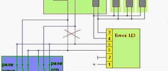
The proposed method on the Internet is this: first of all, we must open our mounting block with fuses and find there the relay responsible for the electric windows.
Having verified it experimentally, namely by turning on the ignition and pulling out the relay, we understand whether the window lifts work or not. If this is what we need, take out the relay.
Then we begin to do some manipulations with the relay by winding wire around it.
I don’t know about you, but I have a question: why do we need this?
We have in our hands an ordinary 4-pin relay, where the principle of operation of the relay is clear to us.
On the Internet they simply suggest that we short-circuit the water contact of the power supply-30 and the output contact of the ESP-87. This will lead to a contact that bypasses the coil (relay), which will only work if it receives power (plus) from the ignition switch (contacts in Relay-85,86-Coil).
So isn’t it easier for us, without making a collective farm, to simply make a jumper to provide power directly?
Make it from a thick wire with a cross-section of 2.5-4 squares so that our jumper does not get hot.
And connect it directly to the block. On the input voltage connector, contact is 30 and output voltage is 87.
Then to turn on the ESP you will not need to turn the ignition key. Since Power (plus) will come to the ESP, bypassing the relay, which will only work when power (plus) is supplied from the ignition switch.
Then there will be no need to farm collectively.
Installation of an additional ESP button in the door of a VAZ 2110, 2111, 2112
I bring to your attention a step-by-step description of the process of installing an additional power window control button (ESP) in the door. The process is not very complicated and time-consuming; everything will take about two hours.
In order to install an additional power window key on the VAZ 2110 door, we will need:
1. 9 meters of wire (I used wires of the following colors: black, yellow, white, 3 meters each) 0.75 mm (section) 2. Button for controlling the ESP (VAZ 2110)* 3. Block for the ESP button 4. Terminals "mother" large - 2 ** 5. Terminals "male" large - 2 ** 6. Terminals "mom" small - 7 ** 7. Terminal "ground" 8mm - 1 8. Blocks for terminals "mother - father" large — 1 (of each type) 9. Plastic clamps (small) — 8 10. Pistons for sprinkling the door trim — 7***
* - in principle, instead of a ten-point rocker button, you can install HIGH-CURRENT (power) buttons from Kalina or Priora, but check with the seller that they are high-current, trigger ones will not work. ** — I didn’t buy these terminals, they came with the pads. *** - they are soft for me, so they didn’t break => I didn’t buy them.
Wiring diagram for the ESP button in the door.
Now we determine the contact numbers on the button and block, according to the diagram:
Okay, we figured it out. The next thing is to find the ESP relay. Typically, the relay is located on top of the mounting block cover. If you have more than one relay installed, then remove them one by one and check if the ESPs are working. The relay, after removing which the ESP stopped working, is the ESP relay.
We remove it from the socket and remove the negative terminal from the battery. Then we disconnect the relay itself from the housing. To do this, use a flat-head screwdriver to slightly press the holder latch and press on its body. The relay holder will disengage. The picture shows the latch:
We are interested in the white wire with a black stripe (this is “+ 12 V” after ignition. If you want the ESP to work regardless of the position of the ignition key, then bridge contacts 30 and 87 of the ESP relay - white with a black stripe and blue with a black stripe) :
We connect our “+12 V” wire to it (according to the diagram, it is connected to pin 2 of the block, I used a yellow wire) Now we need “ground”. You can take it from the door, but the contact there is very unstable, so I took the mass from the bolt behind the mounting block. To see this bolt, open the mounting block and look up and slightly to the right).
Crimp the wire that goes to ground at the ground end and attach it to the bolt. (I used black wire for these purposes)
The next step is to connect the plus from the backlight. I ran into the white wire of the ashtray illumination (I also used a purchased white wire for connection), it is located behind the shield on the left, at the feet of the front passenger.
Do not pay attention to the orange wire (+ to the radio backlight).
Now, we have connected all three wires that we will run into the door to the sources, then we will need to run them through the corrugation inside the door. Remove the center pillar trim (unscrew one screw in the middle and two at the bottom). Also loosen the fastening of the driver's seat belt on the floor (bolt 17).
To make it easier to route the wires through the corrugation, disconnect it from the door.
Unscrew and remove the door handle (two bolts for a Phillips screwdriver). Then we remove the door trim (card), it is best to do this starting from the bottom. Don't forget to unscrew the nail. We find the blocks (male and female) for the ESP engine and disconnect them.
Now the fun begins. We crimp the three wires we have drawn with little mothers and insert them into the block according to the diagram given above. Accordingly, “+12 V” - (yellow) contact 2
, plus backlight (white wire) -
4
, and ground - black - by
5
.
There are 4 contacts left: 1,3,6,7. We connect the original wire (green with a black stripe) that went to the ESP engine block to 6
, and the orange wire to
3
.
Now the block that will be connected to the ESP engine block: blue wire - 7
, brown -
1
contact.
Here, in fact, is the photo (all numbers and designations are in accordance with the diagram above):
Location of wires in the block:
I tidied this mess up a bit:
We connect the button, connect the ESP relay and the minus to the battery. Let's check... if everything works, put all the parts in the reverse order of disassembly. If the glass works normally with the native ESP buttons, but with the connected ones it goes in the opposite direction, swap 3-6, and 7-1 (was 3 - became 6, was 6 - became 3, etc.) contacts in pads that connect to the original wiring in the door. But first, check that the connection according to the diagram is correct.
Replacing the window regulator
If the VAZ-2114 window regulator does not work, it can be replaced with a new one. To do this you need to do the following:
- Using a 10 mm wrench, unscrew the three nuts that hold the glass guide.
- Using a size 8 wrench, unscrew the three nuts that secure the electric motor or manual drive gearbox.
- Disconnect the glass mounting bracket from the glass holder. To do this, you need to unscrew the two 8mm bolts on the bracket.
After this, you can pull the window regulator out of the door. The glass must remain raised. Otherwise it will be impossible to remove the mechanism.
The new lift is installed in the reverse order. However, there is no need to rush to tighten the glass mounting bracket. First you need to make sure that the glass is in the correct position in the guides and moves clearly in them.
Scheme of operation and troubleshooting of window regulators
There are cases when, due to a relay malfunction or a blown fuse, the Priora's power windows stop functioning on the rear doors or on the driver's right. Often the smoothness of their work turns into a pulsating state. What to do in this case? This is a traditional malfunction in VAZ cars; it occurs more often in early production models that have a power window control unit with a built-in ESP electronic unit. This problem is caused by burnt-out electric drive microcircuits or a faulty fuse, which was the result of imperfections in the microcircuit itself. Subsequently, some defects were eliminated by the plant, but the frequency of unit failure is high. But this does not mean at all that one can immediately conclude that the unit is faulty and its subsequent replacement. The reason for this behavior of the window regulators may be completely independent of the operation of the unit itself.
Reasons for poor performance
There are not so many reasons why the VAZ-2114 window regulator does not work well. Conventionally, they can be divided into mechanical and electrical. Let's consider the main ones:
- Glass distortion. Often the reason for poor performance is not the window lifting mechanism itself, but a violation of the position of the glass relative to its guides. This can happen either due to the bracket fastening being unscrewed, or the damp rubber fixing the glass in the holder has ceased to perform its functions. This option occurs much less frequently.
- Contamination of the guide rubbers. The glass moves inside the grooves formed by the rubber bands. These grooves tend to become clogged with dirt. It, like an abrasive, increases the friction force, which creates resistance to glass movement.
- The window lift mechanism is dirty. During operation, drivers do not realize that maintenance is also necessary inside the doors. This is especially true for the cable mechanism. Over the years, not only does contamination occur, but also the lubricant of the mechanism and cables dry out, which increases the friction force. The front left window regulator fails faster due to more frequent use.
- The next reason is wear of the plastic teeth of the mechanism drive. In this case, when you press the control button, you can hear the electric motor running, but the glass does not move.
- Broken cables. This occurs due to attempts to open frozen windows. With repeated loads exceeding the rated ones, the cables begin to delaminate and gradually fail.
Electrical reasons can be reduced to either a short circuit or loss of contact in the VAZ-2114 power window circuit.
Replacement cost
Replacing VAZ-2114 window regulators is cheaper than installing electric mechanisms to replace manual ones. If, in order to simply change the window regulator, you need to disassemble the door trim, dismantle the old mechanism and install a new one, then to install an electric version instead of a manual one, you need to partially disassemble the instrument panel, select a power source and run the wiring from it inside the door. This work requires the intervention of an electrician. Because power cannot be taken from anywhere: the source must match the power of the electric drive, and in the event of a short circuit, the fuses must protect the main wiring of the car. In addition, the power windows must operate when the ignition switch is on.
To summarize, we can say that in the first case, the qualifications of the work are minimal, and it can be done by yourself, without having specific knowledge, while working with an electrician requires a specialist who needs to be paid.
The price of a VAZ-2114 window lifter ranges from 2.5 thousand to 3.5 thousand rubles, depending on the design and manufacturer. But as was said earlier: the lever and rack and pinion options are preferable. If you buy a device for only one side, then the left front window regulator will be more expensive, since it is more in demand.