Purpose and principle of operation
This article describes the idle air control valve. Its structure, purpose, and operating principle are given. The design of the idle speed controller РХХ-60 is considered. The IAC malfunctions are described in detail. Describes how to check the idle air control. The sequence for replacing the idle air control valve is outlined.
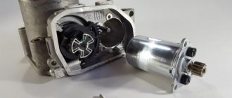
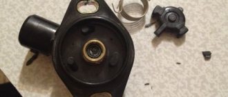
The idle speed regulator РХХ-60 is a two-winding rotary solenoid with a slotted passage hole, the cross-section of which changes according to the program of the electronic control unit. The regulator is connected to the wiring harness using a three-pin socket with a latch.
The purpose of the IAC is to perform the following main functions:
- automatic engine start and warm-up at idle speed;
- stabilization of minimum idle speed;
- control of cyclic air filling at partial loads;
- damping of air flow during sudden opening and closing of the throttle valve.
The principle of operation of the idle air regulator is to regulate the cross-section of the idle air passage channel when an electrical signal acts on the wire winding of the idle air regulator.
An electric current is supplied from the electronic control unit (ECU) to the IAC stator winding, which, interacting with the constant magnetic field of the rotor, generates a control pulse of various duty cycles with a frequency of 125 Hz. In this case, the rotor together with the valve rotates at a given angle and changes the flow area of the bypass channel, through which the intake air enters the throttle space, bypassing the throttle valve. As a result, the engine is supplied with air at idle speed with the throttle valve closed.
The degree of opening of the idle speed control varies from full opening (240 steps) when the engine is started to full closing in the EPH mode; at idle speed the regulator is open by approximately 85...100 steps (35...45%) for a warm engine.
The power supply to the electromagnetic windings of the idle speed regulator, РХХ-60 is carried out from the on-board network through the main relay, and the windings are turned on by connecting them to ground through the power channels of the control unit.
We diagnose engine injection faults ZMZ-406, 405, 409
The ability to recognize the symptoms of typical injection ailments and imagine what a burning yellow lamp threatens will help save nerves, money, time and the engine. If the engine is working properly, the “Check Engine” signal should go out 0.6 seconds after starting - this is enough for the self-diagnosis system to make sure that everything is in order.
1
.
The crankshaft angle position (synchronization) sensor
is the only one whose malfunction will not even allow you to get to the garage. His refusal is an exceptional phenomenon.
If the motor does not show signs of life, inspect the toothed disk, wires, and make sure that the gap between the sensor magnet and the disk is 0.5-1 mm. You can check the sensor itself by measuring the winding resistance with a tester; it should be 880-900 Ohms.
If all other sensors malfunction, the engine will work: the computer will switch to the emergency program.
2
.
The “death” of the camshaft position (phase) sensor
is very difficult for an inexperienced repairman without diagnostic equipment to detect.
Although the engine operates in an abnormal mode of pairwise parallel fuel supply, when each injector fires twice as often (once for each crankshaft revolution), do not try to determine this by ear. The exhaust loses its former purity, but the increase in toxicity can only be caught by measuring the driving cycle. You can tell that the engine is unhealthy by the increased fuel consumption. Another sign of a malfunction is a malfunction of the self-diagnosis system. Failure of the phase sensor will not lead to other unpleasant consequences for the engine.
3
.
If the Volga requires “playing” with the gas pedal when starting up, and has lost its former agility in maximum power and torque modes, the mass air flow sensor
.
The control system, reacting to its failure, “lates” the ignition by 10-12 degrees. In this case, the response to the gas pedal at the beginning of acceleration may even improve. Since the sensor has a CO potentiometer (replacing the oxygen sensor in systems without a converter), the exhaust will become dirtier and the engine will be noticeably more power-hungry. Without requiring the car to be as fast as it used to be, it is quite possible to get home, even if there are several hundred kilometers ahead.
4
.
It is much more difficult to drive with a faulty throttle position sensor
. The symptoms are clearly visible - loss of power, unpleasant jerks and dips during acceleration, unstable idle speed. The engine seems to have been replaced, but the warning light may not light up. The control unit is able to detect a break or short circuit in the sensor and its circuit, but gives in to the “floating” signal.
Driving for a long time with this malfunction is not just unpleasant, but dangerous. Under heavy loads, the computer, without receiving the proper information, will assume that the car is moving in moderate mode, using an economical mixture. Therefore, driving “with the pedal to the floor” will lead to overheating and detonation with all the ensuing consequences. In this case, you should move to the garage or service station slowly, at a gentle pace.
5
.
the coolant temperature sensor
fails , the computer assumes the engine starting temperature is 0°C and gives the corresponding command to the additional air regulator.
A non-optimal ratio of gasoline and air will make starting in cold weather difficult. Within two minutes after the engine is finally started, the computer will decide that the coolant temperature has reached 80°C. So you will have to not only start, but also warm up the engine by operating the gas pedal.
Another trouble awaits the driver when the engine heats up to a temperature close to critical, for example, in the heat, in a traffic jam. The computer, receiving an incorrect signal and considering that the antifreeze temperature is normal, will not adjust the ignition timing. The engine will lose power and detonate.
Idle air control device
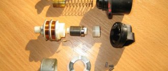
The idle air control, РХХ-60, consists of the following parts, shown at the top in the figure:
- Plug block - 1;
- O-ring - 2;
- Fastening washer - 3;
- Armature axis mounting flange - 4;
- Armature winding - 5;
- Rotary glass - 6;
- Magnet - 7;
- Housing - 8;
- Fixed anchor - 9;
- Armature axis - 10;
- Magnetic core - 11;
- Bearing retaining ring - 12;
- Ball bearing - 13;
- Bearing seal - 14;
- Inlet pipe - 15;
- Rotary valve - 16;
- Emphasis - 17;
- Roller bearing - 18;
- Damper shaft - 19;
- Output pipe - 20;
- The letter x indicates a permanent connection
Malfunctions of the idle speed controller РХХ-60
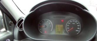
- The malfunction lamp lights up after turning on the ignition. Self-diagnosis of the unit records fault codes 161…166. Check the serviceability of the additional air regulator circuits 37e, 4, 26.
- Check the condition of the bypass channel and, if necessary, flush and clean it of dirt.
- Check to see if the regulator valve is coked, wash the regulator in kerosene and dry it.
Fault codes for the idle air regulator РХХ-60 for the 409.10 engine with the Mikas 7.2 ECU
| Engine fault code 409 | Fault name | Definition conditions |
| 161 | Load short circuit in IAC control circuit 1 (RDV) | After turning on the ignition |
| 162 | Open circuit 1 control IAC (RDV) | After turning on the ignition |
| 163 | Short circuit to ground of IAC control circuit 1 (RDV) | After turning on the ignition |
| 164 | Load short circuit in IAC control circuit 2 (RDV) | After turning on the ignition |
| 165 | Open circuit 2 IAC control (RDV) | After turning on the ignition |
Decoding idle air control fault codes
Fault codes 161, 162, 163, 164, 165, 166 - malfunction of the additional air regulator control circuits. Possible causes of the malfunction: the regulator is not connected to the ECM wiring harness, a break in circuit 37 of the regulator power supply from the main relay, a break in ground wire 14 from the unit, a break or short circuit to ground/on board of the regulator control circuits (4, 26), a malfunction of the power channels of the regulator control ( block outputs: 4, 26), malfunction of the additional air regulator: short circuit of the regulator electromagnet windings (active resistance below 10 Ohms).
Fault codes for the idle speed regulator IAC, engine 40900A with ECU Mikas-11, UAZ 316300
| Engine fault code 40900A | Fault name |
| 0505 | Idle air control circuit malfunction |
| 0506 | Low idle speed (idle speed control locked) |
| 0507 | High idle speed (idle speed control locked) |
| 0508 | Short circuit of the idle speed control stepper control circuit to ground |
| 0509 | Short circuit of the idle speed control stepper control circuit to the on-board network |
| 0511 | Open circuit for idle speed control stepper control |
| 1509 | Idle air control control circuit overload |
| 1513 | Short circuit to ground of idle air control control circuit |
| 1514 | Short circuit to the on-board network or open circuit of the idle air regulator control circuit |
| 1750 | Short circuit to the on-board network of circuit No. 1 for controlling the idle speed regulator |
| 1751 | Open circuit No. 1 for controlling the idle speed regulator |
| 1752 | Short circuit to ground of circuit No. 1 of the idle speed regulator torque control |
| 1753 | Short circuit to the on-board network of circuit No. 2 for controlling the idle speed regulator |
| 1754 | Open circuit No. 2 for controlling the idle speed regulator |
| 1755 | Short circuit to ground of circuit No. 2 of the idle speed regulator torque control |
Decoding IAC fault codes
Fault codes 1750-1755 - malfunction of the additional air regulator control circuits. Possible causes of the malfunction: the regulator is not connected to the ECM wiring harness, an open circuit 37 of the regulator power supply from the main relay, a break in ground wire 14 from the unit, an open or short circuit to ground/onboard of the regulator control circuits (4, 26), a malfunction of the power channels of the regulator control ( block outputs: 4, 26), malfunction of the additional air regulator: short circuit of the regulator electromagnet windings (active resistance below 10 Ohms).
Recommendations
Comments 26
Hello! solved a problem?
I changed it for a while and then it started to float again
I have the same thing, it worked fine for six months
I need to try to reflash it
Just the fuel pump or did you replace the entire assembly, along with the fuel sensor?
It came as a kit, pump, glass, level sensor, which by the way is lying
My sensor is also lying
It worked for me too, until I flashed it for Euro 2, a glitch in the factory firmware
When I start it cold, if you touch the pedal, the speed also fluctuates, if you don’t touch the pedal everything is fine...
We need to see what firmware it is. At 799 31 the factory glitch was with the speed floating when cold.
Looks like lambda umbrella 1 or 2. And so the idle regulator is responsible for idle. stroke or throttle sensor. Go for diagnostics, if necessary, ask the reprogrammed one, otherwise you can guess for a long time. And for the future, buy and install an on-board vehicle so as not to pay diagnosticians. Washing the throttle is unlikely to help because the revs are floating and not standing. Don’t worry, go to a diagnostician.
What onboard tool do you recommend to diagnose and remove errors? From operating experience
Every man to his own taste. Who likes what for the purpose of exploitation. The main thing is that the on-board vehicle is compatible with the brains of your car. I prefer the multitronic 580. But I use skat2. When I bought skat2 multitronic 580 they didn’t produce it. And so, in my opinion, they found a very good place for him in the place of the wind blower. But the main thing is that it produces errors. Many bortoviks have many settings: for example, setting on. and off cooling fan and many others. But there is one But! All this works with the native firmware, if you decide to reflash these settings may not work. What I mean by this is that there is no point in buying an expensive and very sophisticated on-board vehicle; I repeat, it is enough for the on-board engine to read the errors and reset them. And I personally encountered the above.
Read more: Automatic transmission additive Suprotec reviews
Everything they wrote is crap, I also have 405.24 E3. The problem with Mikas et11 is in the firmware, the chiptuner has freely available firmware, anyone who knows even a little can flash it. You can find more details on the gazelle forum, I changed mine and everything is OK. Good luck.
First, look at the weight of the engine, the pigtail on the intake manifold in the area of cylinder 4, and then if that doesn’t help, look further.
Let's start in order 1. Check the spark plugs, or better yet replace them with new ones 2. It's better to replace the explosive wires with new ones too 3. We're looking for air leaks into the manifold past the mass air flow sensor
The MAF.is weird...try to start it without it.
We swam on the working Gazelle only in the morning, I pressed the gas a little and held it for 3 seconds, and then released it and everything leveled out! I have no such problems with Euro 3, I drove on different firmware now Euro 0 works fine, mixed consumption is 11.8 liters, highway 9.5 -10.5 liters
Check the pressure in the fuel rail both at idle and when throttled. It should be at least 2.8 when you press the gas pedal sharply, and so the edge is 3 atmospheres. It is possible that the springs inside the throttle assembly have stretched out (non-removable, replace only) look at what kind of error light is on. If pxx is limited in power and blocked. The culprit is the throttle assembly.
Checking the РХХ-60 for operability
- Connect terminal 2 IAC plus from the battery, and terminal 3 IAC minus. The IAC damper should open completely.
- Connect terminal 2 IAC plus from the battery, and terminal 1 IAC minus. The IAC damper must close completely.
Checking the idle air control regulator РХХ-60 using a Multimeter
- Check the resistance of the IAC windings. Resistance between pins 1-2 and 2-3. Resistance should be 12±1Ohm
- Check for a short circuit (breakdown) between the IAC windings and the IAC housing. Check for short circuit between pins 1, 2, 3 and the housing.
- Measure the resistance between pin 1 and the body, between pin 2 and the body, between pin 3 and the body. It must be at least 1 MOhm.
The most common breakdowns
The most common malfunctions of the idle speed sensor:
- Power failure. This usually happens due to faulty wiring or oxidized electrical contacts. This problem is quite difficult to diagnose due to its inconsistency.
- Rod malfunction due to contamination.
- Electric motor malfunction.
- Worn O-ring.
Rod wear. The shutter movement of a properly functioning idle air control valve should occur without biting or slipping in the gear-screw drive. To assess the condition of the rod and gear-screw, you need to understand how to disassemble the idle air control valve.
Rod contamination is the most common malfunction. When using the device, dirt accumulates in the throttle valve area. If this part has been cleaned for a long time, it is quite possible that problems with the IAC arose precisely because of carbon deposits on the rod. To check the IAC it is necessary to remove it from the throttle assembly. Carburetor cleaner is suitable for treatment.
If there is too much carbon on the rod, it can be dangerous. Because of this, the load on the electric motor increases, which in turn can damage the elements of the IAC control system, which costs more than four hundred euros.
Interchangeability of idle speed controllers РХХ-60
- Idle air regulator РХХ-60, catalog number MP-406-1147051-02, for engine 4213, 409 UAZ, 406 GAZ, MetalPart;
- Idle speed regulator РХХ-60, catalog number 406-1147051-02, for engine 4213, 409 UAZ, 406 GAZ, manufactured by PEGAS.
- Idle air regulator РХХ-60, catalog number 406.1147051-02, for engine 4213, 409 UAZ, 406 GAZ manufactured by UAZ, ORIGINAL.
- Idle air regulator РХХ-60, catalog number 406.1147051-02, for engine 4213, 409 UAZ, 406 GAZ manufactured by Cartronic.
Replacing the idle air regulator RXX-60
- Remove the negative terminal from the battery. This must be done in order not to damage the electronic elements of the Electronic Control Unit (hereinafter referred to as ECU). They consume little current and are very sensitive to voltage drops and stray currents.
- Disconnect the terminal block from the IAC. To do this, press the spring clip down and remove the terminal block.
- Loosen the two clamps on the rubber tubes and remove the tubes.
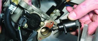
- Unscrew the two M6 bolts with a 10mm wrench and remove the IAC
- Remove the IAC from the clamp
- Place the rubber hose on the new IACs.
- Place a metal clamp over the rubber tube on the IAC
- Secure the IAC with two M6 bolts using a 10mm wrench to the engine receiver
- Place two rubber pipes on the IAC tubular fittings and secure them with clamps
- Connect the terminal block to the IAC.
- Connect the minus terminal to the battery.
