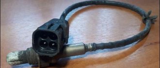
When the fuel sensor does not work , the driver will not be able to calculate how long the fuel in the tank will last. Plus the arrow that shows an empty tank is undoubtedly unnerving. Depending on the type of fuel level sensor (FLS), the most common causes may be abrasion of the resistive elements, damage to the float on the operating lever, or problems with the wiring. However, there are others that are also worth knowing about. Often, checking and basic repair of the sensor can be carried out in a garage. But to diagnose electronic FLS, you will have to seek help from a car service center.
Where is the fuel level sensor located?
To understand why the fuel sensor shows incorrectly or does not work at all, you need to find out where it is located. True, there is no special secret here, because naturally it is located directly in the fuel tank. The only difference that may be is the version of its execution. Depending on the design, it can be built into the fuel module, which is a single device consisting of a fuel sensor, check valve, fuel pump and filter (for injection engines), or installed separately in the middle/side of the gas tank separately, or screwed into a separate device by a separate device. tank if it is a diesel car.
Where is it installed?
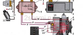
There are two options for installing an RTD: on the fuel rail and in the fuel tank.
The regulator was installed on the fuel rail on cars with a 1.5 liter injection engine. On such engines, two fuel lines come from the fuel tank: direct and return.
The regulator was installed in the fuel tank on cars with a 1.6 liter engine. In such engines, the return line was abandoned. Now the regulator directly relieves pressure in the car tank.
Types of fuel level sensors
Cars can use one of three main types of fuel level sensors. Namely:
- Lever. Refers to the type of float sensors. This is the oldest and simplest type of this device. It consists of a potentiometer (rheostat - variable resistor), a lever, and a float suspended on it. The advantage of a float sensor is its simplicity and reliability of design, as well as its low price. The disadvantage is the large error of the device. In addition, when the car is driven on an uneven road, the instrument needle on the panel often fluctuates, thereby reflecting the movement of fuel in the tank.
- Tubular. It is also float-operated. The design consists of a hollow tube, a float, a guide post, a signal wire (or wires) and a contact group. Provides a fairly high accuracy of fuel level readings, since the float is located in a limited space (inside a hollow tube). A fairly common model of fuel level sensor.
- Electronic. This is the newest type of sensor installed on modern cars and has its own control unit. Its other name is non-contact, which is due to its operating principle. Thus, the operating lever is directly located on the surface of the fuel, and the reading device is connected to it via a magnetic field. The error of such devices is minimal and does not exceed 1%, and often much less.
Please note that even modern sensors are dependent on the quality of the contacts on the connectors (in particular, operating and maintenance conditions). Therefore, any of the listed types of FLS can fail.
Varieties
The design and operating principle of existing FLS have been described above. Thus, all fuel level meters can be divided into contact and non-contact. Representatives of the first type are lever and tubular devices. The lever type is a universal FLS, as it can be installed in any gas tank.
There are several types of contactless FLS:
- Ultrasonic fuel level sensor. It is located on the outside of the fuel tank and the control information unit. Depending on the type of fuel, a specific program is used. These meters are the most explosion-proof.
- For magnetic devices, the sensitive element is hermetically sealed and does not come into contact with the fuel. Information about the fuel level is also transmitted using a float, which is connected to a magnet. The created electrical impulse is read by the device and transmitted to the dashboard, indicating the fuel level in the tank.
- In radio-controlled devices, information is transmitted to the instrument panel using a radio signal. A distinctive feature of these devices is the power supply. They get tangled by the battery, which has a shelf life of about 7 years. They do not depend on the car's battery being charged, so they give more accurate readings.
Based on the transmitted signal, FLS are divided into analog and digital. The first type of instruments gives a large error in readings, so at present it is almost not used. Digital devices convert analog signals into digital data, and then analyze the data and correct errors taking into account the geometry of the fuel tank and uneven fuel levels. The electronic fuel level indicator provides the most reliable information; errors are possible only when physically measuring the volume of fuel.
You can make an FLS with your own hands. To do this, you need to be able to handle a soldering iron and have knowledge of electrical engineering. During manufacturing, it should be taken into account that the signal depends on the fuel level. The design of the device is quite complex. When the fuel drops to a certain level, the float also drops, but the data arrives at the dashboard indicator with some delay.
You can install either an analog or digital fuel level indicator with your own hands. The latter gives more accurate readings, as it can correct and align the received data.
A homemade fuel meter consists of two modules connected by three wires. One is a capacitive sensor module, the other is a display module. The sensor model receives power via two wires. The reflector module receives the signal via the third wire and converts it into an indicator of the fuel level (the author of the video is Vova Grishechko).
Modern sensors: advantages
There are not many situations when the product in question does not work correctly. Most of them happen after 5-10 years of operation of the vehicle, when the mechanical part of the product wears out. The design, materials and tightness of most FLS allow them to function until the vehicle is disposed of. Among the main advantages of the product it should be noted:
- affordable price;
- complete tightness;
- simplicity and reliability of design;
- high level of resistance to mechanical stress.
This is interesting: Troubleshooting and troubleshooting if the oil pressure light comes on at idle
On average, the price of FLS is in the range of 1-2 thousand rubles. If necessary, they can be easily dismantled and replaced. Among the disadvantages of fuel sensors, we highlight the low oxidative resistance of metal plates, as a result of which there is often a discrepancy between the position of the fuel needle on the dashboard and the current level in the tank.
Operating principle of the fuel level sensor
Depending on the principle of operation of the sensors, the malfunctions that may occur with them will differ slightly. Let's look at the operating diagram of each type of fuel level sensor.
Float lever FLS
The operating principle of a float-type level sensor is based on the use of a rheostat. A lever is attached to its central part, at the end of which there is a float. Depending on the fuel level in the tank, the float will move, moving the rheostat lever accordingly along the contact path. During such movement, the resistance will change, which is recorded by the vehicle's electrical system. Accordingly, the arrow on the instrument panel will move in accordance with the indicated resistance on the rheostat. By the way, at a certain position of the float, and therefore the resistance value on the rheostat, a warning lamp on the dashboard will light up, indicating that there is little fuel left in the tank and refueling is necessary.
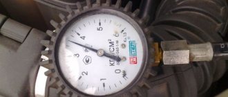
For clarity, let’s look at the operation of the fuel level sensor using the example of VAZ-2108/VAZ-2109, VAZ-21099 cars. Their design can use two sensors - for a high and low dashboard. They are structurally similar, but have different operating resistance. Specifically, for a high panel sensor, a resistance value between 238 and 262 ohms means the fuel tank is empty. With a resistance of 59...71 Ohms, the fuel gauge needle is approximately in the middle (accordingly, the tank is half full). If the resistance is within 17...23 Ohms, then this means that the car’s tank is completely filled.
As for the sensor for the low panel, the situation is similar. So, with a resistance of 285...335 Ohms, the arrow points to an empty tank. At 100...135 Ohms, the arrow will correspond to half, and at a value of 7...25 Ohms - at the end of the scale, pointing to a fully filled tank.
The specified resistances are important in the context of testing the sensor, since if it fails, the first thing to do is to check the internal resistance of the sensor using an electronic multimeter.
Please note that the indicated resistance values are relevant only for the listed VAZ models. For other machines, the corresponding values must be looked for additionally in the technical documentation (manual) attached to them. However, even these indicators can be used as a guide!
Tubular FLS
The design of the sensor is based on a housing with a guide post (actually a tube), at the other end of which there is a wire with a contact group (chip). The design also includes a float with slip rings located inside a hollow tube. The housing flange is secured using mounting bolts on the top wall of the fuel tank. By the way, this is a disadvantage of this type of sensor and imposes a limitation on its use. In particular, tubular type sensors can only be installed on tanks whose height is sufficiently large.
The operating algorithm of the tubular fuel level sensor is as follows:
- On the tube that touches the bottom, in its lower part, there is a hole (or two) through which fuel enters inside.
- The float located inside the tube has contact rings and when moving through the tube, as the fuel level in the tank changes, the resistance also changes. Resistance is measured using one or two contact wires located along the guide tube.
- The movement of the float on the surface of the fuel naturally changes the value of electrical resistance on the contact wire when power is applied to it.
- At the moment when the float is in the upper position (the tank is completely full), a small section of the contact wire is activated, and accordingly, the resistance value is minimal. At the moment when the tank is empty, the float is at the lower extreme point, respectively, the length of the signal wire is maximum, which also corresponds to the maximum electrical resistance.
The resistance of the fuel level sensor will differ for different cars, so when measuring you need to use technical documentation.
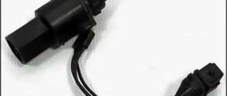
Electronic FLS
Electronic fuel level sensors are installed on cars that use high-quality gasoline and diesel fuel produced on a biological basis. This not only provides very accurate sensor readings, but also allows the actuator to “avoid touching” the fuel directly. However, the peculiarity of using such sensors is that it does not provide smooth monitoring of the fuel level (in small steps). The design of contactless FLS is based on an inactive magnetic sensor. The diagram of the fuel level sensor according to which it works is as follows:
- The main part of the sensor is located in a sealed housing. Only the magnetic sensor (MAPPS) and its lever are in contact with the fuel.
- The movement of the float with a magnet occurs along a sector defined by metal plates of different lengths. A signal corresponding to a certain fuel level in the tank is generated depending on the position of the magnet on a separate plate.
The fuel level indicator in this case is formed using a discrete method since the amplitude of the feedback signal will change from segment to segment that the magnet passes through. Depending on the model of a particular sensor, the signal amplitude and other technical information differ. The operating error of such a system does not exceed 0.5%...1%, but the cost is also significantly higher than a conventional contact system, so these FLS data are installed only on business and premium class cars.
Description of FLS
The FLS is designed to measure and control the fuel level in the fuel tank of a vehicle. Its function is to determine the fuel level, convert it into volume and transmit data for display on an analog or digital device. The regulator indicator is located on the dashboard, allowing the driver to monitor the amount of fuel in the gas tank.
Device and principle of operation
Based on the purpose, you can deduce where the FLS is located. It is installed in the fuel tank. Depending on the type, it can be a separate element or combined with a fuel intake in the case of a carburetor engine. On a car with an injector, it is part of the fuel supply unit.
The most common are contact FLS. Their main element is a potentiometer. The operating principle is based on changing resistance. There are two types of such devices: lever and tubular. They differ in design.
The design of a lever-type device includes a float and a potentiometer connected by a lever. The potentiometer has two sectors, a slider that is in contact with the sectors. One end is connected to the lever, and the other to the float. The float is constantly on the surface. With fuel consumption, it lowers, and the slider moves with it, since they are connected by a lever.
In this case, the resistance of the fuel level sensor changes, the value of which provides information about the volume of the substance. The advantage of these devices is their simplicity of design, the disadvantage is the error of readings, especially for analogue indicators.
The tube type device does not have a potentiometer, but uses the principle by which it works.
The design includes a protective tube with a guide post along which the float moves. The float is connected to a resistance wire, which is connected to the indicator wires. Operating principle: fuel enters the tube through a hole, the float is on the surface and moves depending on the volume of fuel in the tank. The position of the float changes the resistance, which is transmitted to the indicators. A lever device gives more accurate readings, but is used less frequently due to design features: it may not be suitable due to the geometry of the gas tank.
Photo gallery
1. Design of a lever FLS
2. Design of a tubular FLS
The described FLS are not suitable for new types of fuel, as they quickly wear out in an aggressive environment. In this case, non-contact devices are used, such as a passive magnetic position sensor. In these devices, the sensitive element is sealed and does not come into contact with the fuel.
The devices also use a float. It is connected to the permanent magnet by a lever. Moving along the sector on which metal plates of different sizes are fixed, it creates a magnetic field that generates a corresponding electrical signal.
Varieties
The design and operating principle of existing FLS have been described above. Thus, all fuel level meters can be divided into contact and non-contact. Representatives of the first type are lever and tubular devices. The lever type is a universal FLS, as it can be installed in any gas tank.
There are several types of contactless FLS:
- Ultrasonic fuel level sensor. It is located on the outside of the fuel tank and the control information unit. Depending on the type of fuel, a specific program is used. These meters are the most explosion-proof.
- For magnetic devices, the sensitive element is hermetically sealed and does not come into contact with the fuel. Information about the fuel level is also transmitted using a float, which is connected to a magnet. The created electrical impulse is read by the device and transmitted to the dashboard, indicating the fuel level in the tank.
- In radio-controlled devices, information is transmitted to the instrument panel using a radio signal. A distinctive feature of these devices is the power supply. They get tangled by the battery, which has a shelf life of about 7 years. They do not depend on the car's battery being charged, so they give more accurate readings.
Based on the transmitted signal, FLS are divided into analog and digital. The first type of instruments gives a large error in readings, so at present it is almost not used. Digital devices convert analog signals into digital data, and then analyze the data and correct errors taking into account the geometry of the fuel tank and uneven fuel levels. The electronic fuel level indicator provides the most reliable information; errors are possible only when physically measuring the volume of fuel.
You can make an FLS with your own hands. To do this, you need to be able to handle a soldering iron and have knowledge of electrical engineering. During manufacturing, it should be taken into account that the signal depends on the fuel level. The design of the device is quite complex. When the fuel drops to a certain level, the float also drops, but the data arrives at the dashboard indicator with some delay.
You can install either an analog or digital fuel level indicator with your own hands. The latter gives more accurate readings, as it can correct and align the received data.
A homemade fuel meter consists of two modules connected by three wires. One is a capacitive sensor module, the other is a display module. The sensor model receives power via two wires. The reflector module receives the signal via the third wire and converts it into an indicator of the fuel level (the author of the video is Vova Grishechko).
Fuel level sensor malfunctions
Externally, malfunctions of the fuel level sensor manifest themselves in one of the following situations:
- the arrow on the device is constantly in motion, twitching, jumping to extreme positions;
- when the fuel tank is full, the arrow indicates that it is partially filled or that it is completely empty;
- when the ignition is turned on, the needle on the instrument is at the zero mark, provided that there is guaranteed to be fuel in the tank;
If you have similar problems, it means that the fuel level sensor is not working, but if the needle movement does not drop to zero, and the minimum residue signal lamp does not light up or, on the contrary, lights up even when the tank is full, then this indicates a malfunction of the instrument panel itself.
On cars controlled by an ECU, you can find out about the presence of problems with the FLS by the error codes recorded in the RAM block; to do this, just connect a diagnostic scanner to read the memory and check the parameters of the sensors of various systems.
Fuel level sensor errors
The numbers of the main errors that correspond to malfunctions of the fuel level sensor:
- P0460 - “FLS electrical circuit malfunction.” In practice, this means damage or breakage of the power and/or signal wire. Often this is simply a deterioration of contacts due to their oxidation.
- P0461 - “Signal level out of acceptable limits.” An error is generated if the signal from the fuel level sensor is too weak or too strong. This may also be accompanied by interruptions in the fuel supply to the engine, and as a result, a decrease in its power up to a complete stop.
- P0462 - “Low signal level in the FLS circuit.” Usually the error is formed as a result of corrosion of contacts, open ground circuit, short circuit in the circuit, damage to the fuel tank (fuel leak).
- P0463 - “High signal level in the FLS circuit.” As a rule, the error is formed as a result of damage to either the fuel level sensor itself or its float. There are known cases when it occurred due to the fuel tank rusting.
- P0464 - “Unreliable contact in the FLS circuit.” The error is formed as a result of damage to the insulation on the wiring, oxidation of the contacts, interruptions in the transmission of the signal from the sensor to the electronic control unit.
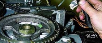
Instructions for replacing and connecting the regulator yourself
To replace it, you need to prepare a set of keys, a new FLS, and know how to remove the fuel level sensor. In order to find out how to connect the FLS, you need to understand the connection diagram.
Fuel level sensor connection diagram
The replacement procedure consists of the following steps:
- Drain the fuel from the tank.
- Next, you need to determine how best to get to the regulator: through the back seat or through the luggage compartment.
- Remove the protective plastic cover from the fuel tank, under which the FLS is located.
- Disconnect the plug with wires from the regulator.
- We unscrew and remove all the tubes by loosening the clamps using a Phillips screwdriver.
- We take out the old FLS and install a new one.
- We make the connection according to the diagram.
- Assembly is carried out in reverse order.
This is interesting: Where are the fuses of the Toyota Corolla 150: block diagram in the cabin
After replacement, you need to fill the tank with fuel and check the operation of the FLS. The indicator should have a value corresponding to the volume of fuel filled.
If the fuel level sensor is faulty, then knowing how to fix it, you can save time and money on visiting a service station.
Causes of malfunction
The reasons why the fuel level sensor does not work or it shows incorrectly are the following faults:
- The float has lost its seal. This situation is relevant when a ball made of fragile plastic is used as a float, which can crack as a result of mechanical stress or as a result of operating the car in severe frosts. In this case, the float will be inside the liquid or, more often, it will simply sink and fall to the bottom. The result will be a constant reading from the device that there is no fuel in the tank. Repair measures include replacing the float or the entire assembly. Another rare option is that the float can simply detach from the lever on which it is attached and “go off on its own.”
- Deformation of the lever that holds the float. As a result, the float may lose mobility or reflect incorrect information. Often this situation occurs when the fuel module is inaccurately removed from the tank, but sometimes even as a result of long-term operation of the car on roads with uneven surfaces, that is, with constant vibrations while driving. You can try to return the lever to its original shape, but most often the corresponding lever is simply replaced with a new one.
- Damage to the sensor housing. As a result, the readings of the resistive elements may change or the lever that takes the corresponding readings may be damaged. In this case, the reason why the sensor does not show the fuel level correctly is the use of low-quality gasoline or mechanical shock loads on the part.
- Failure of resistive elements. This is a fairly common reason why the fuel level sensor does not work. Elements on the rheostat fail for natural reasons, that is, as a result of abrasion during long-term use. It is possible that the wear is partial, for example, in the middle. In this case, the instrument needle will twitch. It is also possible that there is no contact between the sliding element and the resistive track due to damage or wear of the resistive coating or loosening of the slider foot pressure. With such a malfunction, the arrow will lie at zero.
- Lack of electrical contact in a certain section of the circuit. As a rule, on contacts that are oxidized either by moisture or fuel. The wires, their insulation, or breakage may be damaged. There are also sometimes problems with electrical connectors.
- The signal wire has a short to ground. In this case, the value of its resistance will be distorted and tend to zero. With such a malfunction, the level sensor incorrectly displays the level, transmitting information that the tank is completely filled.
- The fuse responsible for the operation of the fuel level sensor has blown. The fuse number must be found in the electrical diagram of the specific vehicle.
- Failure to secure the sensor on the fuel tank body. For example, with a skew. As a rule, in such a situation, the smell of fuel spreads outwards, in particular, the smell of gasoline will be heard in the cabin.
- There are cases when the resistive board on which the slider moves simply falls off the fastening solder.
- Tubular fuel level sensors may have a broken signal wire. In this case, the arrow will constantly show an empty tank.
- Also, tubular sensors are characterized by a coating that can form on the guide post. This will naturally make it difficult (and even impossible) for the float to move. Plaque is usually formed as a result of using low-quality fuel (with a large amount of paraffin, gasoline instead of gasoline). In this case, the instrument needle will freeze in one position, and not necessarily in one of the extreme ones.
- For non-contact sensors, the magnetic sensor and/or its wiring may be damaged. Some of them have a special control and control board installed. The problem may be with her too. In this case, the sensor usually fails completely, that is, it does not indicate the fuel level at all.
Most often, problems arise with floats or resistive elements, which wear out over time and stop transmitting correct data. But note that when the fuel level is not displayed, it is not always the sensor that is to blame. Often the arrow does not work, and here the device on the panel, which, in fact, is a potentiometer, is to blame. Therefore, if the fuel sensor does not indicate the fuel correctly, then you need to remove it and check it with a multimeter and make a visual inspection.
How to check the fuel level sensor
The first thing to do when checking any fuel level sensor is to check whether power is supplied to it through the fuse. If the design of the car does not allow open access to the sensor, then you need to use the car's electrical circuit and connect to the corresponding terminals on the blocks. To do this you will need to use pieces of wire. If there is access (usually through the trunk or under the rear seat), then you need to disconnect the chip from the sensor and then use an electronic multimeter to check or test.
To understand which contacts you need to connect to, use the wiring diagram, but if you are dealing with a conventional resistive level sensor of an injection car, then as a guide you can look at the cross-section of the wires suitable for the block - the wires for the fuel pump are always thicker than for the sensor. In general terms, the verification algorithm will be as follows:
- With one tester probe, touch the positive terminal on the chip, and with the other, touch the negative terminal or the body of the car (it is advisable to choose a place where there is either no paint coating at all or it is minimal).
- If power comes in, the multimeter will show +12 Volts (in standard passenger cars).
If there is no power, first you need to check the integrity of the fuse, and then the integrity of the plus and minus wires. When there is power, but the fuel sensor shows incorrect data, you need to continue checking and make sure what the problem is - in the sensor or wiring.
Checking the fuel level sensor using the universal method
After checking whether power is supplied from the fuse to the fuel sensor, it is necessary to check both the operation of the sensor itself and the signals sent from it to the potentiometer on the dashboard, that is, the fuel level device.
There are three wires between the fuel sensor and the potentiometer used in cars with a carburetor engine. One of which is “ground”, the second is the resistance signal wire going to the device, and the third is the signal wire to the critical fuel level warning lamp!
There are four wires between the sensors and potentiometers on injection motors. The first is “ground”, the second is power to the fuel pump, the third is signal, the fourth is to signal lamp. There are also three wires between the electronic sensors and the device. The first two are power and ground, and the third is a signal going to the control unit, which will indicate the amount of fuel on the digital display of the dashboard.
When checking a float or tubular fuel level sensor, it makes sense to start with a universal method. It is performed in two versions - when the arrow is constantly at the beginning of the scale and when the arrow is constantly at the end of the scale. Let's start with the first one. To do this you need:
- Provide access to the sensor contact group on the fuel tank.
- Turn on the ignition.
- Break the signal wire circuit (using additional wires).
- Observe the behavior of the level indicator on the instrument panel.
If after this the arrow on the device moves to the end of the scale, the fuel level sensor is faulty. If the arrow remains in place, you need to check the integrity of the signal wire, that is, “ring” it.
If the arrow is constantly at the end of the scale, then the sensor is checked according to the following algorithm:
- Provide access to the sensor contact group above the gas tank.
- Turn on the ignition.
- The end of the signal wire going to the tidy is alternately shorted first to the sensor contact, and then to the body (“ground”).
- If the instrument needle remains at the zero mark in both cases, this means that, most likely, the signal wire connecting the sensor to the instrument has broken. Therefore, it needs to be called.
- If the arrow deviates in the opposite direction if the wire is shorted to the body, it means there is no contact of the sensor with ground.
- If the arrow moves in both cases, it means that the sensor is faulty and further diagnostics are required.
For more accurate diagnostics, it is better to check the fuel level sensor when it is removed.
During dismantling, make sure that debris from the cap or seal rim does not fall into the fuel tank. Therefore, before dismantling, it is advisable to wipe off the dust and dirt on the fuel module cover with a rag.
How to check a lever fuel level sensor with a multimeter
We will consider a specific example of how to check a float-type lever fuel level sensor in a removed state based on the VAZ-2108, VAZ-2109 and VAZ-21099 cars. The verification algorithm will be as follows:
- Turn on the multimeter in resistance measurement mode.
- We connect probes to the sensor terminals and move the resistive lever along the track. The resistance under different modes should gradually change.
- So, if the correction hangs below under its own weight (corresponds to an empty tank), then the resistance on the sensor should be in the range of 238...262 or 285...335 Ohms, depending on which sensor is used. If you raise the float down, the resistance should drop to 17...23 or 7...25 Ohms. In practice, the indicated values may differ SIGNIFICANTLY. If the readings differ significantly, do not change, or change abruptly as the float moves, the sensor is most likely faulty.
In addition to measuring the fuel level sensor with a multimeter, you also need to perform a visual check of it. In particular, you need to check the functionality by making sure that the wires and connectors do not have mechanical damage. It is also necessary to inspect the presence of oxides and/or debris on the variable resistance, and the strip with contacts is securely fastened and soldered to the terminals. You also need to check the contact density, that is, how tightly the “tongue” fits the variable resistance. If necessary, it will need to be bent (just be careful!).
On other cars (or when using other sensors), the verification algorithm will be the same, but you must first know the nominal value of the resistance of the installed sensors. This can be found in the instructions for them or in the technical documentation for the car (manual).
Please note that if the fuel level sensor is working, but the indicator on the dashboard still does not work correctly or does not work at all, it means that the indicator itself is faulty. Often repairs involve replacing (or adding) a trim resistor. This is required in order to correct the failed resistance on the device itself.
Fuel level sensor repair
First of all, you need to understand that repairing the fuel level sensor is impossible without removing it from its seat.
If the resistive elements on the lever fuel level sensor are worn out, you can try to bend the “tongue”, which directly slides over them and transmits the current value to the monitoring device. At the same time, you can clean the contact tracks of the device. If the resistive track has worn out significantly, then repair is not possible and the FLS must only be replaced. If a board with a resistive track “walks” in its seat, it needs to be soldered again.
When there is a malfunction in the electrical circuit of the sensor, problems usually occur at the contacts. Accordingly, they need to be cleaned and tightened. It is also advisable to lubricate them with a special lubricant. If the wires are damaged, it is advisable to replace them with new ones (you can use a whole bundle). However, if the damage to the insulation is minor, you can use electrical tape or heat shrink for wires for repairs.
If the guide tube in the tubular sensor is dirty, it means that it needs to be cleaned and the deposits washed off using a spray with a cleaner. At the same time, you can also clean the signal wires located along the tube.
The disadvantage of the electronic fuel level sensor is its non-repairability. At least in a garage environment. Therefore, if this unit fails, contact a car service center or an official representative of your car manufacturer for help.
When is it necessary to change the sensor?
The fuel sensor must be replaced if at least one of the following reasons occurs:
- contacts are so destroyed that there is nothing left to protect;
- resistive tracks are worn to the limit;
- there is damage to the float. This is rare, but it happens. Ruptures lead to the fact that the latter fills with gasoline and sinks, showing an empty or half-empty tank,
- even when it is full;
- The slider itself is damaged.
In case of the above-mentioned defects, the FLS must be replaced.