Engine repair is considered the most difficult thing in a car, because no other part contains such a huge number of interconnected elements. On the one hand, this is very convenient, because if one of them breaks down, there is no need to change the entire assembly; it is enough to simply replace the failed part; on the other hand, the more component elements, the more complex the device and the more difficult it is for those who I'm not very experienced in car repairs. However, with a strong desire, anything is possible, especially if your zeal is supported by theoretical knowledge, for example, in determining the tightening torque of the main and connecting rod bearings. If for now this phrase is a set of incomprehensible words for you, be sure to read this article before getting into the engine.
Sliding bearings, their types and role in the operation of internal combustion engines.
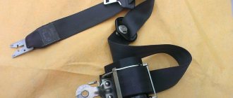
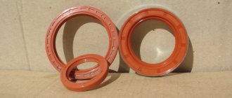
Main and connecting rod bearings are two types of plain bearings. They are produced using the same technology and differ from each other only in the inner diameter (for connecting rod liners this diameter is smaller).
The main task of the liners is to convert translational movements (up and down) into rotational ones and ensure uninterrupted operation of the crankshaft so that it does not wear out prematurely. It is for these purposes that the liners are installed under a strictly defined gap, in which a strictly specified oil pressure is maintained.
If this gap increases, the engine oil pressure in it becomes less, which means that the journals of the gas distribution mechanism, crankshaft, and other important components wear out much faster. Needless to say, too much pressure (reduced clearance) also does not bring anything positive, since it creates additional obstacles in the operation of the crankshaft; it may begin to jam. That is why it is so important to control this gap, which is impossible without using a torque wrench in repair work, knowledge of the necessary parameters that are prescribed by the manufacturer in the technical literature on engine repair, as well as observing the tightening torque of the main and connecting rod bearings. By the way, the tightening force (torque) of the connecting rod and main bearing cap bolts is different.
Please note that the given standards are relevant only when using new sets of parts, since the assembly/disassembly of a previously used unit due to its wear and tear cannot guarantee compliance with the required clearances. Alternatively, in this situation, when tightening the bolts, you can focus on the upper limit of the recommended torque, or you can use special repair bushings with four different sizes, differing from each other by 0.25 mm, provided that the crankshaft is ground until the minimum gap between rubbing elements will not be 0.025/0.05/0.075/0.1/0.125 (depending on the existing gap and the repair product used).
VAZ 2109 engine assembly
Unscrew the crankshaft pulley mounting bolt, holding the shaft from turning.
Remove the crankshaft pulley, timing pulley and timing belt.
To secure the crankshaft from turning, screw the two flywheel mounting bolts into the holes in the crankshaft flange and insert a large screwdriver or spudger between them.
Unscrew the fastening nut and disconnect the bracket from the water pump supply pipe.
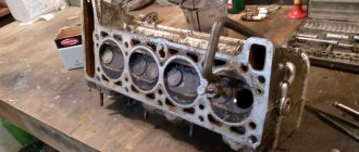
Unscrew the ten bolts securing the cylinder head using a special Allen key
Remove the bolts and washers. Location of the cylinder head bolts
Location of cylinder head bolts
Remove the cylinder head.
Do not jam a screwdriver or other tools between the cylinder head and the cylinder block.
To remove the head from the block, insert a screwdriver under the exhaust manifold. Using it as a lever, lift the head.
Remove the cylinder head gasket
Unscrew the two mounting bolts and remove the water pump supply pipe.
Remove the water pump by prying it up with a screwdriver.
Turn the engine upside down and remove the sixteen oil pan mounting bolts.
Remove the oil pan and sealing gasket.
To remove the oil filter, use a special wrench.
If there is no key and you cannot unscrew the filter by hand, pierce its housing with a screwdriver and unscrew the filter, using the screwdriver as a lever.
Unscrew the oil filter.
Remove the two bolts securing the oil pump receiver to the crankshaft support cover and the bolt securing it to the oil pump.
Remove the receiver tube from the oil pump and remove the receiver.
Remove the six oil pump mounting bolts.
Remove the oil pump by sliding it off the crankshaft nose
Remove the six bolts securing the rear oil seal holder
Carefully remove the holder by pressing it away from the block with a screwdriver.
Unscrew the nuts securing the connecting rod cover.
Remove the connecting rod cover and liner.
If dismantling the cover is difficult, knock it down with gentle blows of a hammer.
Push the connecting rod with the piston inside the cylinder so that the connecting rod does not touch its walls.
Otherwise, the cylinder mirror may be damaged.
Location of connecting rod nuts (yellow arrows) and main bearing cap bolts (red arrows).
Carefully remove the piston assembly with connecting rod and upper liner from the block, being careful not to damage the cylinder bore.
Remove the remaining pistons in the same way.
If the liners remain on the shaft, remove them
Remove the bolts securing the main bearing caps.
Remove the main bearing caps and lower bearings.
Remove the crankshaft from the cylinder block.
Remove the upper main bearing shells from the cylinder block beds. Remove the support half-rings from the middle support
We wash all the parts and blow them with air.
After disassembly you need to check all the parts
Video.
The internal combustion engine structurally has a large number of associated parts, which experience significant loads during operation of the internal combustion engine. For this reason, assembling a motor is a responsible and complex operation, for the successful implementation of which the technological process must be followed. The performance of the entire power unit directly depends on the reliability of fixation and the accuracy of fit of individual elements. For this reason, an important point is the accurate implementation of the calculated interfaces between mating surfaces or friction pairs. In the first case, we are talking about attaching the cylinder head to the cylinder block, since the cylinder head bolts must be pulled with a strictly defined force and in a clearly designated sequence.
As for loaded rubbing pairs, increased demands are placed on the fixation of connecting rod and main plain bearings (main and connecting rod bearings). After engine repair, during the subsequent assembly of the power unit, it is very important to maintain the correct tightening torque of the main and connecting rod bearings of the engine. In this article we will look at why it is necessary to tighten the bearings with a strictly defined force, and also answer the question of what is the tightening torque for the main and connecting rod bearings.
Read in this article
Assembly of a VAZ 21083 gasoline engine
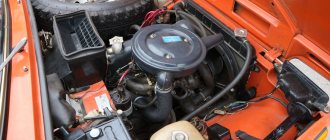
Gasoline engine on the "eight"
The appearance of the VAZ 21083 gasoline engine is directly related to the low quality of domestic rubber products. The fact is that at the very beginning of production, the Lada Samara family of cars was equipped with a VAZ 2108 engine, the first domestic power unit designed specifically for transverse placement under the hood of a front-wheel drive car.
However, the VAZ 2108 engine had an unpleasant feature, also characteristic of foreign engines with a timing belt drive. When the timing belt breaks, the engine pistons meet the cylinder head valves, and the latter inevitably bend, which leads to expensive repairs of the VAZ 2108 engine. On foreign cars, such a breakdown occurred extremely rarely due to the high reliability of timing belts. However, in the first Samaras, the breakage of a low-quality belt was such a frequent occurrence that it was necessary to urgently modify the engine with the help of specialists from German automakers. As a result, a new engine appeared, which became the progenitor of a whole family of power units. Assembling a VAZ 21083 engine is not a difficult task; it can be completed without the help of specialists.
What are plain bearings
To better understand why engine bearings need to be tightened to a certain torque, let's take a look at the functions and purpose of these elements. Let's start with the fact that these sliding bearings interact with one of the most important parts of any internal combustion engine - the crankshaft. In short, the reciprocating motion of the piston in the cylinder is converted into rotational motion precisely thanks to the connecting rods and crankshaft. As a result, torque appears, which is ultimately transmitted to the wheels of the car.
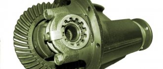
The crankshaft rotates constantly, has a complex shape, experiences significant loads and is an expensive part. To maximize the service life of the element, connecting rod and main bearings are used in the crankshaft design. Taking into account the fact that the crankshaft rotates, as well as a number of other features, conditions are created for this part that minimize wear.
For the manufacture of liners, softer materials are used compared to those from which the crankshaft itself is made. The liners are also additionally coated with an anti-friction layer. Lubricant (motor oil) is supplied under pressure to the place where the liner is connected to the crankshaft journal. The specified pressure is provided by the oil pump of the engine lubrication system. In this case, it is especially important that there is the required clearance between the crankshaft journal and the plain bearing. The quality of lubrication of the rubbing pair, as well as the engine oil pressure in the engine lubrication system, will depend on the size of the gap. If the gap is increased, then the lubricant pressure decreases. As a result, rapid wear of the crankshaft journals occurs, and other loaded components in the internal combustion engine also suffer. In parallel with this, a knock appears in the engine.
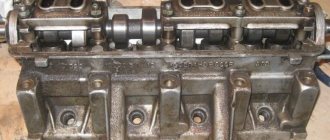
Engine assembly
The engine begins to be assembled by installing the main bearings and crankshaft. Nowadays you can come across liners in different configurations, in the photo the liners are not very well equipped as there are no holes on the liner for the central crankshaft journal, and since this journal does not have a through hole, the lower liner will be starved of oil and this leads to faster wear of the crankshaft journal . So don’t be lazy and drill a couple of holes as shown in the photo below.
Photo. Correct installation of liners in the VAZ 21083 engine block.
Before installing the liners in the bed, carefully wipe the bed with a rag so that nothing gets under the liner; debris under the liner can lead to pinching of the crankshaft and poor heat transfer of the liner to the engine block. Install the half rings immediately as shown in the figure, lubricate the inserts with oil, and also lubricate the half rings inside with oil, then they will not fall out of their places.
Photo. The arrow shows the thrust half-rings of the VAZ 21083 engine
After installing the crankshaft into the block, be sure to check the longitudinal movement of the crankshaft, this can be done with a screwdriver as shown in the photo below, insert it from different sides, if there is movement of the crankshaft, then repair half rings are needed. Here you can already select one repair and the other standard, or lightly grind the half ring on a stone or sandpaper spread on a flat surface. Try to ensure that there is no longitudinal movement of the crankshaft; if there is longitudinal movement, the half rings may fall out during engine operation.
Photo. Checking the longitudinal movement of the crankshaft.
Now you need to put the crankshaft cushions in their places, each cushion must return to its place, you cannot install a cushion from another engine as it will be slightly different in the gap and can either clamp or give way. The photo below shows how to install the pillow correctly, note that the lock of the liner is placed next to the lock of another liner, the photo shows the installation of the third pillow with drilled holes. It doesn’t matter whether the holes are beautifully drilled or not, what is important is that oil will flow through them to the crankshaft journal.
Photo. Correct installation of the crankshaft cushion.
Immediately place all the cushions on the crankshaft but do not tighten, tighten the bolts. Now start tightening one cushion at a time, I always start with the third one, tighten it until the crankshaft is tight, turn it with a wrench as shown in the photo below. And so after each tightened pillow, try to rotate the crankshaft. You need to tighten the pillows well, but do not overdo it, as you can break the bolts. You can read more about the crankshaft in the article Repair of the crankshaft (crankshaft).
Photo. Tightening the crankshaft cushions.
After installing the crankshaft, we begin installing the pistons. The photo below shows how the piston should be installed correctly in the cylinder. You can read more in the article Changing pistons on a VAZ 08-09.
Photo. Correct installation of the piston in the block, the arrow shows the liner lock on the connecting rod.
Before installing the piston into the cylinder, be sure to lubricate the piston rings with oil and do not forget to lubricate the connecting rod bearings with oil.
Photo. Installing the piston into the cylinder using a homemade clamp, which I grasp one ring at a time, insert the oil scraper, and insert the next one with a light blow of the hand.
The pistons and connecting rods are in place, we install the rear cover, but do not forget to replace the old oil seal with a new one, I do not put a gasket under this cover, I apply sealant.
Photo. Rear engine cover of VAZ 2108.
Before installing the flywheel, use a chisel to make a clearer groove along the factory mark, since the factory mark is very thin and can be difficult to find on the flywheel when it is in the engine.
Photo. Mark on the flywheel of the VAZ 21083 engine
The correct way to install the flywheel is to place the fourth piston at the very top as shown in the photo, the mark should be at the top.
Photo. Correctly installed flywheel on a VAZ 21083 engine
Be sure to lubricate the bolt threads with sealant when tightening the flywheel, since in the crankshaft there are through threads that are not coated with sealant and a bolt that is not coated with sealant can leak oil into the clutch disc.
Photo. The bolt is coated with sealant when tightening the flywheel.
To easily and firmly tighten the flywheel, you can use the method shown in the photo below. Block the connecting rod with the pipe and tighten the bolts with the head.
Photo. Flywheel tightening.
After installing the flywheel, you need to install the clutch disc correctly; if you put it in the opposite direction, the clutch will not work. In the photo below you see the clutch disc and basket, the arrow shows the protruding washer of the clutch disc, it should fit into the basket. As shown in the photo, this is how it should be installed; the input shaft from the classic box is ideal as a clutch disk centering mandrel.
Photo. Correct installation of the clutch disc.
Photo. A twisted basket with a centering shaft, after which this shaft is pulled out, the shaft gives precise alignment of the clutch disc, without a centering shaft it is very difficult to correctly center the clutch disc. And this may prevent you from putting the engine on the box, since the box shaft will rest against the clutch disc.
Photo. Shaft in the clutch disc.
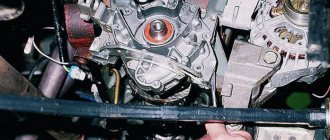
Now you can install the front cover (oil pump), do not forget to replace the oil seal with a new one, touch the oil pump to the crankshaft groove. I don’t put a gasket under this cover; I use sealants. Install the timing belt drive key and gear. Screw on the front crankshaft pulley.
Photo. Tightening the front crankshaft pulley.
Before installing the oil receiver, be sure to coat the tip of the tube with sealant, this will prevent air from leaking into the oil pump; if this is not done, the old rubber gasket will poison the air, which will lead to poor oil pressure.
Photo. Installing an oil receiver on a VAZ 21083 engine
Now you can screw on the oil sensor and pan.
Photo. Engine before installing the sump.
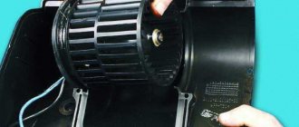
All that remains is to screw on the pump, but in order not to make a mistake on how to install it correctly, you can use the hole in the pump to guide you, it should look down the engine, this hole is shown in the photo.
Photo. VAZ 21083 engine pump.
Photo. VAZ 21083 engine with installed pump.
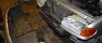
Since I removed the engine without a head, it means that I will install it without a head through the bottom, but for ease of installation, you can cut off a piece of tin from the hole in the gearbox boot, as shown in the photo below.
How to tighten main bearings and connecting rod bearings
So, taking into account the above, it becomes clear that the tightening torque of the main and connecting rod bearings is extremely important. Now let's move on to the assembly process itself.
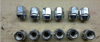
- First of all, molar liners are installed in the bed of the molar necks. Please note that the middle liner is different from the others. Before installing the bearings, the preservative lubricant is removed, after which a little motor oil is applied to the surface. After this, the bed covers are placed, after which the tightening is carried out. The tightening torque should be that recommended for the specific model of the power unit. For example, for engines on the VAZ 2108 model, this figure can be from 68 to 84 Nm.
- Next, the connecting rod bearings are installed. During assembly, it is necessary to accurately install the covers in place. The specified covers are marked, that is, their arbitrary installation is not allowed. The tightening torque of the connecting rod bearings is slightly less compared to the main bearings (the indicator ranges from 43 to 53 Nm). For Lada Priora, the main bearings are tightened with a torque of 68.31-84.38, and the connecting rod bearings have a tightening torque of 43.3-53.5.
Let's sum it up
Although the tightening torque of the main and connecting rod bearing caps is an important parameter, quite often the torque value is not indicated in the general technical manual for the operation of a particular vehicle. For this reason, you should separately look for the necessary data in special literature on the repair and maintenance of a particular type of internal combustion engine. This must be done before installation, which will allow you to carry out repair work correctly and also avoid possible consequences.
For this reason, tightening is carried out using a torque wrench and taking into account a precisely defined force. Do not forget that the tightening torque of the connecting rod and main bearing cap bolts is somewhat different.
Why does the crankshaft liners turn: the main reasons. What to do if the connecting rod bearing has turned, how to change the connecting rod bearings correctly.
The appearance of knocking noises in different diesel operating modes. Fault diagnosis. The nature of the knocks of the crank mechanism, timing gear, and fuel equipment.
When it is necessary to bore the engine crankshaft, what is crankshaft boring for? How the crankshaft is bored, features of the selection of liners.
What should be understood by the definition of “knocked engine”. Why does the engine start knocking? In what cases does a knocking sound in the engine indicate a breakdown of the internal combustion engine.
Is it worth doing chip tuning of a production car engine: the advantages and disadvantages of such modifications. Engine life and maintenance after chipping, tips.
Purpose and design of the crankshaft of an internal combustion engine.