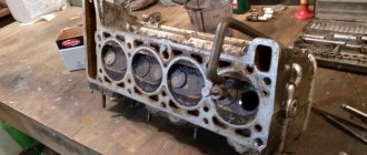
09.25.2021 8 411 Cylinder block
Author: Victor
Many owners of Lada Priora, in the process of car maintenance and repair, independently replace the head gasket or grind valves. When performing such work, it is important to observe the sequence and tightening torque of the cylinder head on the Priora.
[Hide]
In what cases is it necessary to tighten the block?
During the operation of any car, including the VAZ 2170 Priora, the engine head is exposed to long-term cyclic effects of gases located in the engine cylinders. On older power units, the tightening of the cylinder head screws could weaken under such loads and periodically needed to be brought to a normal level. Today, all VAZ Priora engines use bolts made of special steel, which are tightened once for their entire service life.
If a coolant and oil leak occurs, there is no point in further tightening and tightening these bolts, since this will not improve the tightness of the joint. The only correct way to combat a leak is to remove the head, check the evenness of the mating surfaces and replace the gasket. After performing any repair work related to removing the head from the engine, it must be tightened in compliance with all necessary conditions.
The video from the author Alex ZW shows the process of installing the cylinder head on an 8-valve engine.
Other cases in which dismantling of the cylinder head is required
Of course, it is not necessary to remove the cylinder head for every breakdown. This is only necessary if major repairs are needed. Such “major” cases include:
- Gasket wear.
- Formation of carbon deposits on parts.
- Valve deformation.
- Need to replace guide bushings.
- Failure of the camshaft, etc.
Of course, repairing it yourself or through a service in any case involves certain financial costs. To ensure smooth operation of the engine, regular diagnostics of the cylinder head are necessary. It is recommended to use high-quality fuel. In addition, try to prevent the car from overheating - because of this, the cylinder head may lead.
If some points remain unclear to you, then you can visually familiarize yourself with the process of replacing valves by watching the video:
Dear friends, today we will tell you in detail and with photographs how to independently replace valve stem seals on VAZ-2112, 2111 and 2112 equipped with a 16-valve engine. The beauty of our story is that in order to replace the oil caps we will not remove the head from the engine, and this is a significant saving of time and labor costs, there is no need to drain the antifreeze, unscrew the manifold, etc. At the same time, we will do this without using an expensive valve depressurizer, which allows us to do this, but will use a regular valve depressurizer for the VAZ-2110, which can be bought on the car market for 200 rubles. Even before starting work, I recommend purchasing this desiccant, if you have little experience in desiccaning and drying, then take a stock of heels of crackers, we will also need an anaerobic (do not use silicone) sealant, unlike conventional silicone, when in contact with oil, it does not clog the channels but dissolves in it, and also buy a key for tensioning the timing pulley for 50 rubles, since the belt will have to be removed and then set according to the marks. By the way, it wouldn’t hurt to replace the timing belt and rollers at the same time, ideally. If you are ready to do it yourself - no problem, if you lack determination - I can recommend contacting the guys in Minsk to replace the timing belt, they will definitely do it well and inexpensively. Well, if you’re ready to do everything yourself, then let’s get started. First, remove the plastic cover from the engine and gain access to the “intake manifold”
Nuances of work
At different times, Lada Priora cars were equipped with engines with a displacement of 1.6 and 1.8 liters and a different number of valves in the heads - V8 (or 8V) and V16 (or 16V). The type of unit head determines the size of the bolts, the order of their installation and the tightening torque of the cylinder head on the Priora.
If the car has an 8-valve engine, then it can use head mounting bolts of different sizes:
- on old motors 21114, M12*1.25 hex head screws are used;
- on more modern 21116, which went into production approximately in mid-2011, M10*1.25 elements with an asterisk head are installed.
When installing a removed head, it is necessary to use new screws, since the old ones will be stretched and have internal damage.
Also, the engines use gaskets of different designs - combined on the old unit and all-iron on the new one. The procedure for tightening bolts for engines with metal and combined gaskets is absolutely identical.
The main nuances when performing work are checking the length of the fasteners, observing the sequence of tightening the screws and monitoring the tightening force. Violation of these conditions leads to damage to parts and the need for additional repair work. The procedure itself is not complicated and can be done independently in any convenient place - in a garage or in an open parking lot, with the exception of the case of installing the head on the engine, which is preferably installed indoors.
It is important to remember that tightening the bolts “by eye” without a torque wrench is unacceptable, since a uniform fit of the mating surfaces of the head and block will not be ensured.
Tools and materials
Before starting the tightening procedure, you should prepare everything necessary to perform:
- wrench with built-in dynamometer up to 100 H⋅m;
- a set of sockets and regular keys;
- Togh E14 key;
- calipers for measuring the remaining length of bolts;
- plate with a marked scale up to 180 degrees;
- new bolts.
A torque wrench is an important tool for DIY repairs.
Step-by-step instruction
Sequence of operation on an 8 valve engine:
- Wipe the cylinder head surfaces and dry the bolt holes in the engine block.
- Install the gasket on the block and align it along the guides.
- Mount the head on top and insert 10 M10 or M12 mounting bolts. If the owner decides to save money and keep the old screws, then they should have a length of no more than 135.5 mm.
- Tighten the elements according to the diagram. The tightening force should not exceed 20 N⋅m.
- Then you need to re-tighten the bolts. The second tightening force should be in the range from 70 to 85 N⋅m.
- Next, you need to tighten the screws by 90 degrees in the same sequence. The rotation angle can be controlled using a special device, which is a plate with an attached scale from 0 to 180 degrees.
- In accordance with the regulations, you need to tighten the bolts again by 90 degrees.
- The attachment of the 8 valve head to the block is complete.
- After assembling the motor, you need to check the quality of operation by starting and warming up the engine. A securely tightened joint between the head and the block should not allow working fluids to leak from the crankcase of the power unit.
Homemade device for controlling the rotation angle
If a more powerful and modern engine with sixteen valves is installed on a car, for example, the VAZ 21126 model or 126 for short, the procedure for pulling the bolts has its own characteristics.
In order to correctly tighten the cylinder head screws on such units, you need to:
- Remove oil from the mating surfaces and check that there is no liquid in the bolt holes.
- Install the gasket, center it and place the head on top.
- Insert 10 mounting screws M10*1.25 into the guide holes, having previously lubricated the threads with engine oil. If you decide to use old bolts, which is permissible for 16 valve heads, then their remaining length should not exceed 98 mm.
- Perform preliminary pulling according to the scheme with a torque of 12-20 N⋅m.
- Increase the tightening degree to 26-34 N⋅m and re-run all the bolts in the same sequence.
- Then you need to tighten the screws 90 degrees, with a force of about 50 N⋅m.
- Repeat tightening by 90 degrees again, the torque on the key will be approximately 80 N⋅m. Some instructions recommend waiting up to 20 minutes between turns, but in practice no advantages of such a scheme have been identified.
- After assembling the power unit, you should check the quality of the work performed.
The procedure for pulling the head on 1.8 liter engines, which are 1.6 liter engines with an enlarged cylinder, is completely identical to that described above.
If during the work process the correct moment of force is applied to the bolts, corresponding to design calculations, then the gasket will be evenly and tightly pressed along the joint, ensuring a reliable and tight connection. It is important to note that if it is necessary to remove the cylinder head from the engine, then the screws are also loosened according to the scheme established by the regulations. Chaotic unscrewing of the elements will lead to deformation of the head and the appearance of invisible microcracks.
crank mechanism
The correct tightening torque for the cylinder head on a VAZ-2114
This main engine unit consists mainly of the following groups:
Each part of the group has several additional elements. For example, each piston carries a set of O-rings, a connecting pin and pin retaining clips. The crankshaft has bearings and oil seals. The most interesting thing is the structure of the connecting rods.
The principle of operation of the mechanism
VAZ engines, like other cars, are based on explosive combustion of fuel. The piston creates a certain compression of the air-gasoline mixture, a spark from the spark generator ignites it, pushing the piston down, and the crank mechanism (CPM) converts translational motion into rotational motion. This occurs due to the special shape of the crankshaft. The mounting points of the connecting rods are located so that while the connecting rods pushing the pistons rise, the connecting rods pushed by the piston are lowered. And this process takes place in shifts.
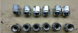
Set of connecting rods "Priors"
These parts are collapsible. The main part is made of high quality metal. Only in the upper ring, where the piston locking pin fits, is an insert made of a different metal installed. In general, the connecting rod consists of the following parts:
- connecting rod;
- liner covers;
- coupling bolts 2 pcs.;
- special washers;
- connecting rod bearing.
This is due to the fact that the liners have special grooves for the passage of engine oil. Due to the high rotation speed, this unit requires uniform and abundant lubrication. The slightest discrepancy between these grooves and the oil supply holes of the crankshaft will lead to a disruption in the flow of lubricant and, as a result, jamming of the engine.
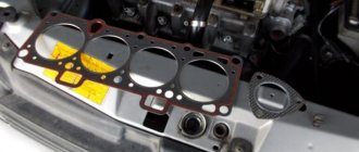
Photo gallery
The photo below shows the procedure for loosening the bolts and tightening them, which must be taken into account when repairing the cylinder head on a VAZ 2170 Priora.
Scheme for loosening bolts on an engine with 8 valves
Scheme for loosening bolts on an engine with 16 valves
16 valve head tightening diagram
8 valve head tightening diagram
VAZ 2170 | Appendix: Tightening torques for threaded connections | Priora
ENGINE
| Detail | Thread | Tightening torque, N*m (kgf*m) |
| Cylinder head bolts | M12x1.25 | see section “Engine” |
| Intake pipe mounting nut | M8 | 20,83-25,73 (2,13-2,63) |
| Tension roller nut | M10x1.25 | 33,32-41,16 (3,4-4,2) |
| Camshaft bearing housing nut | M8 | 18,33-22,64 (1,87-2,3) |
| Camshaft pulley bolt | M10x1.25 | 45,82-56,6 (4,68-5,78) |
| Accessory drive housing bolt | M6 | 6,66-8,23 (0,68-0,83) |
| Cooling jacket outlet pipe mounting nut | M8 | 9,8-22,5 (1,0-2,3) |
| Main bearing cap bolt | M10x1.25 | 68,31-84,38 (6,97-8,61) |
| Oil sump bolt | M6 | 5,1-8,23 (0,52-0,84) |
| Balance shaft gear bolt | M10x1.25 | 45,82-56,6 (4,68-5,78) |
| Connecting rod cover nut | M9x1 | 43,32-53,51 (4,42-5,46) |
| Flywheel bolt | M10x1.25 | 70,81-87,47 (7,22-8,92) |
| Water pump mounting bolt | M6 | 5,10-8,23 (0,52-0,84) |
| Crankshaft pulley bolt | M12x1.25 | 87,47-108,05 (8,93-11,03) |
| Water pump inlet pipe mounting bolt | M6 | 4,2-5,1 (0,43-0,52) |
| Muffler exhaust pipe fastening nut | M8x1.25 | 19,6-24,5 (2,0-2,5) |
| Bolts for securing the front and rear suspension brackets of the power unit | M10x1.25 | 31,85-51,45 (3,25-5,25) |
| Nuts of bolts securing the suspension supports of the power unit | M10x1.25 | 28,08-45,3 (2,86-4,62) |
| Nuts for fastening the left suspension bracket of the power unit | M8 | 14,0-22,54 (1,43-2,3) |
| Bolt securing the oil receiver to the main bearing cover | M6 | 6,37-10,29 (0,65-1,05) |
| Bolt securing the oil receiver to the pump | M6 | 6,37-10,29 (0,65-1,05) |
| Oil pump mounting bolt | M6 | 8,33-10,29 (0,85-1,05) |
| Oil pump housing bolt | M6 | 6,97-8,61 (0,71-0,88) |
| Oil pump pressure reducing valve plug | M16x1.5 | 45,5-73,5 (4,6-7,5) |
| Oil filter fitting | M20x1.5 | 37,49-87,47 (3,82-8,92) |
| Carburetor mounting nuts | M8 | 6,6-15,4 (0,7-1,6) |
CLUTCH
| Detail | Thread | Tightening torque, N*m (kgf*m) |
| Bolt securing the clutch housing to the engine cylinder block | M12x1.25 | 54,2-87,6 (5,5-8,9) |
| Clutch housing cover bolt | M6 | 4,7-7,7 (0,49-0,79) |
| Nut securing the clutch housing to the gearbox housing | M8 | 15,7-25,5 (1,6-2,6) |
| Bolt securing clutch to flywheel | M8 | 19,1-30,9 (1,95-3,15) |
TRANSMISSION
| Detail | Thread | Tightening torque, N*m (kgf*m) |
| Hinge bolt on gear selector rod | M8x1 | 16,3–20,1 (1,66–2,05) |
| Gear selector mounting bolt | M6 | 5,1–8,2 (0,5–0,83) |
| Nut securing the gear shift rod clamp | M8 | 15,7–25,5 (1,6–2,6) |
| Nut of the rear end of the primary and secondary shafts | M20x1.5 | 120,8–149,2 (12,3–15,2) |
| Reversing light switch | M14x1.5 | 28,4–45,3 (2,9–4,6) |
| Bolt securing the gear fork to the rod | M8x1 | 11,7–18,6 (1,2–1,9) |
| Nut fastening the jet thrust to the power unit | M10x1.25 | 51–82,4 (5,2–8,4) |
| Speedometer drive fastening nut | M6 | 4,5–7,2 (0,45–0,73) |
| Ball joint race fastening nut | M8x1.25 | 15,9–25,8 (1,6–2,6) |
| Gear selector shaft mounting bolt | M6 | 7,8–12,3 (0,8–1,26) |
| Nut securing the rear crankcase cover | M8x1.25 | 15,7–25,5 (1,6–2,6) |
| Retainer plug | M16x1.5 | 28,4–45,3 (2,9–4,6) |
| Attaching the gear selector lever to the rod | M8x1 | 28,4–35,0 (2,9–3,6) |
| Nut securing the gearbox to the clutch housing | M8x1.25 | 15,7–25,5 (1,6–2,6) |
| Drain plug | M22x1.5 | 28,7–46,3 (2,9–4,7) |
| Clutch fork support | M8 | 15,7–25,5 (1,6–2,6) |
| Clutch release bearing guide bushing bolt | M6 | 3,8–6,2 (0,39–0,63) |
FRONT SUSPENSION
| Detail | Thread | Tightening torque, N*m (kgf*m) |
| Nut securing the upper support to the body | M8 | 19,6–24,2 (2,0–2,47) |
| Nut securing the ball joint to the suspension arm | M12x1.25 | 77,3–96 (7,9–9,8) |
| Bolt securing the ball joint to the steering knuckle | M10x1.25 | 49–61,7 (5,0–6,3) |
| Nut securing the lever to the subframe | M10x1.25 | 59,7–73,5 (6,0–7,5) |
| Nut securing the extension to the lever | M12x1.25 | 102,9–127 (10,5–13,0) |
| Telescopic stand housing nut | M48x1 | 117,5–147 (12–15) |
| Nut securing the brace to the subframe | M14x1.5 | 117,5–147 (12–15) |
| Nut securing the stabilizer to the lever | M10x1.25 | 42–52 (4,29–5,3) |
| Nut securing the stabilizer to the subframe | M8 | 12,9–15,9 (1,32–1,63) |
| Nut securing the telescopic rod rod to the upper support | M12x1.25 | 52,6–64,6 (5,35–6,6) |
| Nut securing the strut to the steering knuckle | M12x1.25 | 103–127,2 (10,5–13,0) |
| Nut securing the left side member of the subframe | M8 | 19,6–24,2 (2,0–2,47) |
| Bolt securing the subframe to the body | M12x1.25 | 83–103 (8,5–10,5) |
STEERING
| Detail | Thread | Tightening torque, N*m (kgf*m) |
| Steering gear housing clamp nut | M8 | 15,0–18,6 (1,5–1,9) |
| Steering shaft bracket mounting nut | M8 | 15,0–18,6 (1,5–1,9) |
| Bolt securing the steering shaft to the gear | M8 | 15,0–18,6 (1,5–1,9) |
| Steering wheel nut | M16x1.5 | 31,4–51 (3,2–5,2) |
| Locknut for outer steering linkage | M12x1.25 | 27,0–33,4 (2,8–3,4) |
| Bolt securing the connector to the subframe | M8x1.25 | 19,6–24,2 (2,0–2,47) |
| Steering rod ball pin nut | M12x1.25 | 27,05–33,4 (2,76–3,41) |
BRAKE SYSTEM
| Detail | Thread | Tightening torque, N*m (kgf*m) |
| Bolt securing the wheel cylinder to the brake shield | M6 | 3,31–7,72 (0,34–0,78) |
| Front wheel hub nut | M20x1.5 | 186,3–225,6 (19–23) |
| Bolt securing the shoe guide to the steering knuckle | M10x1.25 | 49–62 (5,0–6,3) |
| Bolt securing the caliper to the guide pin | M8 | 31–38 (3,16–3,87) |
| Rear brake to axle bolt | M10x1.25 | 34,3–42,6 (3,5–4,3) |
| Nut securing the master cylinder to the vacuum booster | M8 | 9,8–15,7 (1,0–1,6) |
| Nut securing the vacuum booster to the bulkhead | M8 | 9,8–15,7 (1,0–1,6) |
| Nut securing the pressure regulator to the body | M6 | 3,31–7,72 (0,34–0,79) |
| Manual brake lever lever bolt | M8 | 10,36–24,18 (1,06–2,47) |
Video “Installing and tightening the cylinder head on a Priora”
The assembly of the upper part of a 16 valve engine is presented in a video from the Expert R channel.
Do you have any questions? Specialists and readers of the AUTODVIG website will help you ask a question
Was this article helpful?
Thank you for your opinion!
The article was useful. Please share the information with your friends.
Yes (100.00%)
No
X
Please write what is wrong and leave recommendations on the article
Cancel reply
Rate this article: ( 3 votes, average: 5.00 out of 5)
Discuss the article:
Let's move on to the cylinder block
We remove the pallet. Rotating the crankshaft as it is convenient for us, unscrew two bolts on each connecting rod cap. We use a TORX E10 head for this.
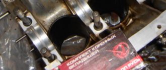
We take out the pistons along with the connecting rods. To do this, use the wooden handle of a hammer to press the connecting rod from below and lightly tap it to knock it up. We remove the old liners and buy new ones of the same size according to the markings on them. Here is another stone in AvtoVAZ’s garden, the owner has never climbed into the car from the interior or into the engine, but three pistons were of group “B” and one was “C”. It turns out that at the factory they re-sharpened one cylinder a little and simply put an enlarged piston there, no words. There are no options, we take group “C”, don’t sharpen the engine because of this. We will not touch the main liners either.
We buy a new piston group that does not bend the valves, connecting rods and connecting rod bearings.
General rules for performing work, methods used
There are a number of general rules that must be followed when installing the block head:
- It is important to strictly observe the tightening torque. For these purposes, a special tool is used - a torque wrench. It is not recommended to perform this operation with regular keys;
- The head bolts must be pulled smoothly, jerking is not allowed. Since the tightening force on the last approaches is significant, extending the wrench arm with a pipe can simplify the procedure and ensure smooth, uniform tightening;
- Before installing the bolts, you need to carefully inspect the condition of the threads on them. There should be no dirt or foreign particles on the coils.
- The threads of fasteners should be lubricated with engine oil before tightening. But you should not pour grease into the holes for the bolts (especially for “blind” holes), since in the future it will not allow the fasteners to be fully tightened.
Despite the fact that each engine has its own characteristics of tightening the cylinder head, the general technology of this operation is the same. In general, two methods are used to tighten fasteners:
- In several approaches, bringing the tightening force to the required value;
- Tightening the fasteners to a certain force (in one or more approaches), and then tightening the bolts twice to a certain angle.
The tightening method is selected based on the type of bolts.
The first method is used when using non-stretching bolts (these are not used now, but they can be found on old cars). But often this type of fasteners requires tightening after a certain period of engine operation in order to compensate for the shrinkage of the cylinder head gasket. But such fasteners are allowed for reuse, and more than once.
The second method of tightening the block is relevant for most modern cars. And all due to the use of tensile bolts (the so-called TTY type).
Such fasteners, due to elastic deformation, are able to compensate for thermal expansion of the head and shrinkage of the gasket, but for this they need to be put into deformation mode (in fact, just stretched a little).
To do this, it is necessary to tighten the bolts twice to a certain angle. On some cars this angle is 45 degrees, on others it is 90 degrees.
But after the elements are put into elastic deformation mode, they will no longer be able to return to their original state, and therefore their reuse is not allowed due to the high probability of destruction.
Consequences of incorrect cylinder head installation
Correct tightening of the cylinder head is very important, since the performance of the motor directly depends on it. The cylinder head acts as a cylinder cover, and any violations in its fit affect the processes occurring inside the power unit.
Insufficient tightening of the head leads to a drop in compression due to loss of tightness at the junction of the cylinder head with the cylinder block, burnout of the gasket, breakthrough of working gases from the cylinders and their entry into the channels of the lubrication or cooling systems, penetration of technical fluids into the combustion chambers, which in turn is negative affects the functioning of the power unit and can cause very serious damage.
Excessive tightening also does not bring anything good; in this case, damage to the head often occurs - cracks appear, or fasteners are destroyed - bolts break, threads break, etc.
Loading "How to properly tighten bolts in this"
In the cylinder head video, a master with extensive experience describes in detail and shows how to correctly tighten the cylinder head bolts. On a Lada Priora with 16 cl, the work of the unit is carried out according to the same scheme.
- How to change oil in a Lada Priora gearbox
- replace Like a timing belt on a Priora with your own Subtleties
- by hand selecting and replacing 16-valve spark plugs for Priora engines
Author: Serj ratings. ( 1 Zav, average: 5.00 out of 5) Loading... Share Source
- When coolant gets into the oil, traces of whitish liquid remain on the dipstick.
- White smoke comes out of the muffler, caused by antifreeze getting into the cylinders.
- When exhaust gases enter the cooling system, bubbles are visible in the conservator or radiator.
- Oil stains have appeared on the surface of the condenser or radiator. They indicate that lubricating fluid has entered the cooling system.
Preparing tools and consumables for replacement
Tools you will need:
- set of heads;
- flat blade screwdriver;
- a set of keys;
- torque wrench;
- hex wrench;
- pliers.
- Using asbestos.
- Non-asbestos.
- Using metal components.
The power unit 21124 is equipped with a non-asbestos, non-shrink gasket with a metal edging. The 21126 engine uses a metal seal with two layers. The 11194 motor uses the same gasket, but with a hole diameter of 76.5 mm. Cylinder head seals for power units 21124 and 21124 are not interchangeable.
Step-by-step instructions for replacing the cylinder head seal
- We de-energize the car by disconnecting the negative terminal on the battery.
- To get to the cylinder head, it is necessary to dismantle the decorative plastic protection of the motor. To do this, disconnect the plug with wires from the adsorber purge valve. We move aside the valve with hoses from the engine.
- We unscrew the cap on the oil filler neck, as it will not allow you to remove the casing. After removing the protection, you need to screw it back so that foreign objects do not get into the motor.
- We remove the housing clamps from the studs, pull it up and remove it from the car.
- We set the piston of the 1st cylinder to the TDC position so as not to disrupt the valve timing. To do this, we combine the marks on the shaft pulleys, and you also need to combine the mark on the flywheel with the triangular cutout on the clutch housing.
- If the procedure is performed after a trip, relieve the pressure in the fuel system.
- Next, drain the antifreeze from the cooling system. To do this, unscrew the cap from the expansion tank to reduce the pressure. Then we go under the bottom of the car and unscrew the drain plugs alternately on the cylinder block and the cooling jacket, substituting the prepared container. We wait until all the liquid has drained and screw the plugs into place.
- We dismantle the air filter along with the air supply hose.
- Disconnect the plug with the TPS and IAC wires.
- Disconnect the air supply hose from the throttle assembly.
- Remove the throttle cable from the throttle assembly.
- Loosen the clamps and disconnect all the hoses going to the throttle assembly.
- We unscrew the throttle assembly fasteners and disconnect it from the intake manifold studs.
- We dismantle the throttle assembly.
- We turn off the power to the ignition coils, dismantle them and unscrew the spark plugs.
- Disconnect the plug with wires from the corresponding sensors.
- Loosen the clamps holding the cooling system hoses. Disconnect 5 hoses from the thermostat.
- Disconnect the plug with wires from the coolant indicator sensor.
- Unscrew the fastening of the ground wire tip and disconnect it.
- Unscrew the fastening of the fuel system hose fitting and disconnect it from the fuel wire. A rubber seal is installed on the tip. When reassembling, it must be replaced if it has defects.
- We unscrew the bolt on the clamping plate of the bracket, thanks to which the fuel wire is attached to the cylinder head. We remove the plate.
- We unscrew the fastening screw and disconnect the ground wire from the cylinder head.
- We dismantle the intake manifold by unscrewing its fasteners to the valve cover and cylinder head.
- We unscrew the mounting bolts of the valve cover to the cylinder head and dismantle it.
- Using a hexagon, unscrew the fasteners of the front protective cover of the timing drive and remove it.
- Then unscrew the fasteners of the lower front protective cover of the timing drive.
- Loosen the belt tensioner nut.
- Remove the timing belt.
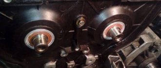
- We unscrew the fastenings of the camshaft sprockets, holding them from turning.
- We remove the gears from the shafts.
- We remove the keys from the grooves of the shanks on the shaft.
- We dismantle the tension and support rollers.
- Remove the rear timing drive protection.
- Unscrew the cylinder head mounting bolts. The order of unscrewing is the reverse of the order of tightening.
- We measure their length. It should not exceed 98 mm. If there is a discrepancy, replace the bolts.
- We dismantle the cylinder head together, as it is too heavy.
- Remove the cylinder head gasket.
- We carefully clean the contacting surfaces from dirt and oil stains, ensuring they are clean and dry.
- We clean the threaded holes for the mounting bolts in the block from oil residues.
- Before installing a new seal, check that the mounting sleeves are present in the sockets. If they remain in the cylinder head, press them into the block until it stops.
- We install a new cylinder head seal on the cylinder block.
- We check the coincidence of the marks on the shafts.
- We mount the cylinder head on the block. We tighten the mounting bolts according to the diagram, the torque indicated in the Lada Priora manual.
- We install all the parts that were removed on the engine, attach the hoses, and connect the plugs with wires.
- We adjust the timing belt and generator.
How to remove the cylinder head of a Lada Priora.
You can wrap the car engine block head yourself. However, for this you need to know that the tightening torque of the cylinder head bolts of the VAZ 2112 16 valves and 8 valves are different. This is justified by the different design of internal combustion engines. The user manual describes the reasons when work needs to be done. Oil leakage from the contact points between the block and the head. Usually expressed in the appearance of dark streaks on the walls of the block, or the formation of sweaty spots on the contact surface. The appearance of a whitish emulsion on the filler cap and dipstick. This is a sign of antifreeze leaking into the crankcase compartment. It may also be accompanied by foaming of the liquid in the expansion tank and the appearance of oily films there. Burnout of the gasket. Usually accompanied by the smell of gasoline from the cooling system or oil. While the engine is running, fuel under pressure seeps into the compartments where the lubricant or antifreeze dissolves. Major repairs of the internal combustion engine, usually the cause is overheating, maintenance of the piston group or serious breakdowns. After dismantling the old head and installing a new one. If there is no urgent need to climb into the engine structure , there are no lubricant leaks anywhere, there is no need to perform the procedure. Bolt tightening diagram for cylinder head VAZ 2112 16 valves When performing work, tightening rules must be strictly observed. For the 16 valve engine model 2112, the permissible bolt length is 94 mm. If the indicator is 95 millimeters, the parts should be replaced. Some experts even recommend installing new pins for each procedure - this is guaranteed to ensure high-quality operation of the system. Separately, it is required to adhere to the sequence of tightening the nodes - this guarantees an even fit of the surfaces and the absence of leaks in the future. The last point is the force applied during work. The indicator is critically important, as it ensures tightness and sealing of the block. Tightening torque of the VAZ 2112 cylinder head bolts. The force is measured in newtons per square meter. The standard tightening scheme for a 16 valve head does not require any special frills: tighten all 10 bolts in the correct sequence with a force of 20 N/m; wait 2 minutes and turn the caps 90 degrees; after 3-4 minutes. repeat the previous point. Note! Tightening is performed in a similar way for VAZ Priora 21126. The manufacturer strongly recommends that you follow the procedure. The longevity of the entire power plant depends on the correct tightening. If the bolts are not tightened enough, oil leaks may occur or antifreeze may enter the crankcase. If excessive force is applied, the bolts break, which will require a major overhaul of the block with drilling out the remaining threads. A more terrible process occurs when the sequence is not followed. If the tightening is weak, you can go through the key again and everything will return to normal. Here, deformation of the head itself is possible - the torque is large and the assembly can move due to improper distribution of force, which inevitably causes repeated disassembly of the internal combustion engine and grinding of the planes. In severe cases, the engine is sent for remelting. Procedure for tightening cylinder head bolts VAZ 2112 16 valves Reference sequence of actions. Completely degrease the flat surfaces of the block and head, allow to dry. Remove all debris and dust from the bolt sockets. If there is debris left inside, you won't be able to tighten the studs all the way - this could result in the threads licking. Calibrate the guides and install a new seal. Only a metal gasket is used; the use of sealants, adhesives, and oils is strictly prohibited. Prepare the cylinder head for docking, first install and lubricate all components. Place the head on the gasket and lower the studs into the seats, after wetting them with a thin layer of motor oil. Tighten the bolts in the sequence indicated on figure with a force of 20 N/m. (this is the first circle) Next, turn the elements 90 degrees and leave alone for 3 minutes. By analogy, repeat step No. 7. After this, you can continue assembling the engine as normal. Conclusions Covering the cylinder head on the Lada 2112 does not require sophisticated equipment or deep knowledge mechanics. The procedure is performed using a torque wrench and a set of sockets. Leave a review
What is a cylinder head?
In order to carry out any manipulations with this unit, it is necessary to understand the purpose and operating principle of the device. The cylinder head on the VAZ-2112 model we are considering is made of two options: cast iron, aluminum. Essentially, to put it bluntly, this is the engine cover.
One of the most important components of a vehicle, which is responsible for:
- combustion of gasoline in the engine;
- removal of exhaust gases during the combustion process.
Secondary functions performed by the cylinder head:
- the functional option is carried out thanks to the work of support washers, valve bushings and other parts located in the head;
- thanks to the hole in it, the chain tensioner and the drive of the pulley distributor are installed.
The abbreviation cylinder head is used more often in the terminology of automotive components, since there is not always time to pronounce long and complex names. But it is clear that you need to know all the decryptions. Especially if it is an internal combustion engine (internal combustion engine) and cylinder head (cylinder head).
Therefore, the tension moment must always be adjusted and not carelessly, but correctly, otherwise its functionality will be impaired.
First of all, this is necessary to avoid moisture accumulation at the junction of components in the block and their connections. Thanks to this protection, condensate collects on a special plane to allow liquid to leak out of the engine.