Why are fuses needed?
Fuse links are required in the on-board network as a protective element. Each line provides a small safety margin, but in case of a short circuit this is not enough. In the event of a critical power surge, the wires or powered part may melt or ignite, which leads to serious consequences for the car.
Fuse links are calibrated by the factory to a certain threshold. When the mark is exceeded, the thin element is destroyed and the circuit opens, which “saves” the entire machine from fire.
Where is the main and interior fuse box of the VAZ 2114 located?
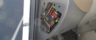
The car is equipped with two main mounting panels. The first part is installed inside the engine compartment. You can find the module on the left side in the direction of travel of the car. It is distinguished by a black or orange plastic cover. You can get to the fuse links and relays by opening the protective cover. This is done by pressing two latches.
The second part is mounted inside the cabin under the dashboard. To access the panel, you will need to open the service hatch in the front passenger's feet on the left side of the heater casing. Unscrewing 4 screws opens the panel itself. Here are relays and fusible links that control the operation of the main components of the machine.
Location of VAZ 2114 fuses in the main block
On the fourteenth Lada model, in 90% of cases two types of mounting blocks are used. The location of the internal parts and the pinout of the fuses of the VAZ 2114 are not significant, but they are different. Therefore, it is most convenient to consider both options separately.
Note!
Some modifications of the vehicle may be equipped with other module designs. You can find out the name of the variety on the inside of the lid.
Fuses for VAZ 2114 injector (block 3722010-60)
The module contains fuse links and automatic circuit breakers. All elements are marked in order.
Main unit relay
- 1 – Head optics wiper switch;
- 2 – Contact insert breaker of the turn signal and hazard warning signal mechanism;
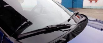
- 3 – Responsible for the proper operation of the windshield wipers;
- 4 – Fuse for monitoring stop lines and vehicle lighting;
- 5 – Power supply to electrical accessories (window regulators);
- 6 – Horn control, main circuit;
- 7 – Power line for heating the aft glazing;
- 8-9 – respectively, control of high and low beam head optics.
Decoding the fuse diagram of the VAZ 2114 head unit
- F1 – fog lights at the rear of the car;
- F2 – control circuit for turn signals and hazard warning switch;
- F3 – power supply to the interior and luggage compartment lamps, also ignition indication, ECM;
- F4 – fuse for the aft wind window heating relay circuit; the portable lamp contact is also energized here;
- F5 – fuse for the signal of the VAZ 2114 and the head fan of the cooling system;
- F6 – is fully responsible for the electrical package circuit;
- F7 - standard fuse for the VAZ 2114 heater, also responsible for electric drives for the windshield washer, glove compartment lighting and headlight wipers;
- F8/9 – fusible links responsible for the front fog lights;
- F10/11 – backlight for the left and right sides, respectively, also responsible for illuminating license plates, cigarette lighter, and instrument panel;
- F12/13 – light fuse for VAZ 2114 for low-range mode on the right and left sides, respectively;
- F14/15 – similarly for the long-range lighting mode on both sides of the car separately;
- F16 - VAZ 2114 instrument panel fuses are responsible for indicating sensors and device status.
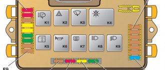
Main relays and fuses for VAZ 2114 in block type 3722010-18
A more modern modification, installed on cars since 2010. Here the arrangement of elements and fusible links is more thought out. Thanks to a more logical layout, individual elements are easier to access.
At the same time, not only the location of the fuses is different, their functionality and area of responsibility are also changed.
Head relays
- 1 – optical wipers;
- 2 – is responsible for the switch for turn signals and emergency lights;
- 3 – cleaners for the front part of the car glass;
- 4 – module for serviceability of lighting elements and backlight;
- 5 – control of the electrical package circuit;
- 6 – horn power supply;
- 7 – power conductors for heating the rear window;
- 8-9 – circuit breakers for high and low beam head optics, respectively.
Deciphering the VAZ 2114 fuse box diagram
- F1 – headlight cleaner contact connectors, also refers to the sprinkler tank motor activation valve;
- F2 – turns and opens the alarm when activated;
- F3 – illumination of the interior space of the cabin, power supply circuit for the side lights of the rear part of the vehicle;
- F4 – cigarette lighter fuse for VAZ 2114, overload protection for the heating element of the rear window, this also includes a portable lamp;
- F5 – VAZ 2114 fan fuse is responsible for cooling the antifreeze, also responsible for the horn;
- F6 – power supply for windows and electrical accessories;
- F7 – control lines for the front and rear sets of headlight and windshield washers – a complete circuit of equipment, this also includes the glove compartment lighting;
- F8/9 – front fog lights for the right and left sides, respectively;
- F10 – fuse for the lighting of the VAZ 2114, the cigarette lighter, the instrument panel indication, the engine compartment lighting, also the left side of the side light;
- F11 – separately for the right side of the side lights;
- F12-15 – power supply for head optics, complete lighting set;
- F16 – fuse for VAZ 2114 instruments, also coolant temperature indicators, voltmeter.
Purpose of fuses
What fuses are on the VAZ 2114? The electrical circuit of this car is designed in such a way that in front of all the main electrical units there are chargers located in the fuse box.
VAZ 2114 fuse diagram
The connection diagram of these protective devices is shown in the figure.
- F1 - rated insert current 10 A - protects the fog lamps located at the rear.
- F2 - with a current of 10 A - these are left and right turn lights, an emergency warning light, a relay-breaker for turn lights and emergency lights.
- F3 - with a current of 7.5 A - protection of light bulbs in the cabin and trunk, trip computer circuits, ignition and brake lights, "Check engine" warning light.
- F4 - with a current of 20 A - protects switches located in the heating circuit of the trunk door glass and heating elements of this glass, “carrying” contacts.
- F5 - with a current of 20 A - protects the horn circuit and its switch, as well as the electric motor of the cooling system fan.
- F6 - with a current of 30 A - this is a circuit of electric windows and their switches with contacts.
- F7 - with a current of 30 A - a protective device for three electrical units - a heater, a windshield washer and a headlight cleaner. In addition, there is also a cigarette lighter, glove compartment lighting and winding for the heating switch for the trunk door glass.
- F8 - with a current of 7.5 A - is protection for the right fog light bulb located in front.
- F9 - with a current of 7.5 A - this is protection for the left fog light bulb located in front.
- F10 - with a current of 7.5 A - protects the indicator lights on the left side, the license plate number, the engine compartment light, the dashboard lights and switches with heating levers, as well as the indicator lights for the size.
- F11 - with a current of 7.5 A - protects the right-side headlight bulbs.
- F12 - with a current of 7.5 A - a protective device for the right low beam headlight bulb.
- F13 - with a current of 7.5 A - a protective device for the left low beam headlight bulb.
- F14 - with a current of 7.5 A - protects the left high beam headlight and the blue high beam warning light.
- F15 - with a current of 7.5 A - protects the right high beam headlight.
- F16 - with a current of 15 A - protects the light bulbs and the turn switch and hazard warning lights, the white reverse light, the power supply of the instrument cluster, the trip computer, the generator winding (at startup), the lights indicating low oil pressure, brake fluid and parking brake, battery discharge.
Cabin fuses for VAZ 2114 - decoding of circuits and areas of responsibility
A separate fuse panel for the cabin unit is designed to control secondary circuits of electrical equipment. The main task of the module is to relieve the engine compartment and minimize the likelihood of breakdowns due to board overload.
In 90% of cases, the mounting block is equipped with a small set of inserts. This is due to the intended purpose of the device. In fact, such modules are installed here.
Relay
In the mounting panel, the control relays are arranged in sequence from left to right:
- Control of the fuel pump power cores. From here voltage is supplied to the main line.
- Main engine relay. Responsible for powering the ECU and parallel circuits of the primary control system of the vehicle.
- Breaker element for the power cores of the main fan of the engine cooling system.
There is also a similar number of fuse links. Each element works in tandem with a relay and is responsible for protecting the system from overload:
- F1 – VAZ 2114 fuel pump fuse, is responsible for monitoring the correct supply of voltage to the main line;
- F2 – fuse VAZ 2114 injector 8 valves, responsible for controlling the voltage of the car’s main circuit;
- F3 – fuse link going to the electronic control unit.
Where is it located and how can you remove the fuse box in the VAZ-2115
Of course, in order to look for a problem in a particular component of the car, you need to know its location. In the VAZ-2115, the designers decided to move the fuse box to the engine compartment - in the first generation Samara it was located in the cabin. Finding the block will not be difficult - it is located in a black box, near the left glass. Let's look at the decoding of the fuses located there. In particular:
- K1 – is responsible for the headlight cleaning system relay;
- K2 – alarm and relay for the turn signal switching system;
- K3 – windshield cleaning system;
- K4 – control of lamp performance;
- K5 – electric windows;
- K6 – sound signals;
- K7 – heated rear window;
- K8 – high beam;
- K9 – low beam.
It is worth drawing your attention to one more point. There is also a fuse box in the cabin
It should also be described in more detail. Here, in particular, there are 3 relays and fuses, as well as an electronic control unit. If we look at this block from top to bottom, we will see the following picture. The fuses will be distributed in the following order:
- 15-amp, responsible for the operation of the fuel pump;
- 7.5-amp - it is equipped with speed, crankshaft and mass air flow sensors, a valve located on the adsorber purge, and an electric fan relay;
- 7.5-amp - the electronic control unit is powered through it.
In addition, this block also contains 3 relays. One of them is the main thing. The other two are responsible for turning on the fuel pump and the electric cooling fan, respectively.
Replacing the fuse box located in the engine compartment is a very simple procedure, and every car enthusiast can do it without any problems. To do this, you only need to perform a few simple steps, spending a couple of minutes on everything.
In particular, first of all, for safety reasons, we remove the negative terminal from the battery. Next, remove the lid from the black box. After this, you should unscrew the two nuts - for this you will need a 10mm wrench. At the next stage, you need to disconnect the upper and lower connectors. In order to perform the last of these operations, it is necessary to lift the block. That's all. Now all that remains is to pull out the fuse box. In order to put it in place, all the manipulations described above are carried out in the reverse order.
An even simpler procedure is to replace the fuses themselves. The main thing here is to determine which one has failed. Next, everything is done very simply. The faulty fuse is removed from the corresponding socket and a new one is installed in its place. We recommend using tweezers for this simple manipulation. The thing is that fuses are small in size and have a flat shape. If your fingers are too thick, or, for example, your hands are frozen, this simple device will allow you to easily replace them without dropping anything.
To determine whether a fuse has failed or is functional, you can use one of the two most common methods. The first of these is a visual inspection. To do this, the suspect fuse should be removed from the socket and the conductive part should be inspected for integrity.
However, the problem is not always visible to the naked eye. Therefore, a more reliable and accurate method of checking the functionality of fuses is the following. It’s worth warning right away - it’s a little more complicated than the first option. So, to check, you should first turn on a non-working consumer of electricity, for example, high beam headlights. Next, without removing the fuse, we check the voltage at both ends. If it is missing somewhere, you can safely conclude that this element is faulty.
One more, very important piece of advice. Before replacing a blown fuse, you should find the reason why it failed. Otherwise, you risk repeating the replacement manipulations again. Frequently blown fuses may well indicate problems with the electrical wiring. If you do not have the necessary knowledge, then it would be best to turn to specialists, since delaying solving the problem can ultimately result in more serious consequences than a burnt-out protection element.
Removing the head unit
In some situations, it may be necessary to remove the mounting block. This is usually caused by voltage surges or part of the circuit burning out. Also, if fuses burn out on a VAZ 2114, the reason may be hidden in oxidized or melted tracks or connecting terminals.
When asked how to remove the fuse box on a VAZ 2114, you must follow the simple dismantling instructions:
- open the negative terminal on the battery;
- from the inside of the cabin, you will need to disconnect the five main connectors of the wiring harnesses;
- dismantle the cover of the mounting block by clamping two terminals;
- the sixth pin connector is disconnected on the top side of the module;
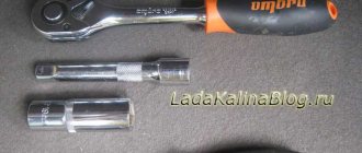
- using a key No. 10 with an adapter, you need to unscrew the fastening of the main module;
- lift the mounting diagram with a screwdriver;
- remove the last terminal blocks from the bottom side;
- remove the mounting device.
Reinstallation is performed in the opposite order. The simplicity of the procedure is due to the fact that all terminals are different from each other and it is impossible to confuse their location.
Fuse box for injection VAZ 2115 electrical diagram
UAZ 3303 Zhivchik Logbook Installation of add. fuse box in UAZ 3303
A fairly common problem in domestic cars is the problem of breakdown of any electrical devices. In this case, the only way out is to check the condition of the fuses. Today we will talk in more detail about the fuses of the VAZ 2115 car on an injection engine. The fuse box of the VAZ 2115 car consists of two lines with fuses and this entire structure is secured with a nut to the vehicle body.
If you decide to remove the fuse lines, you will need to disconnect the battery.
So, this article provides answers to these fairly common questions:
- What is the fuse box on a VAZ 2115?
- How does the electrical circuit of a VAZ 2115 car work?
- How to properly install, repair and dismantle the mounting block?
Description of the fuse box
The fuses in a VAZ 2115 car are located in a special mounting block, which is located in the air supply box on the left side of the vehicle. The mounting block of the VAZ 2115 car includes all the most important sections of electronic circuits, while supplying them with the necessary fuses and relays. In addition, this device greatly simplifies the installation and repair work on circuits, because all wiring and relays are located in one place, and therefore their replacement is quite easy.
In the event of any breakdown of electronic equipment, the current in the node that is responsible for this device will increase, resulting in a short circuit.
The wire through which the current passes to the fuse burns out and melts, as a result of which the circuit breaks and the device turns off, but its integrity is maintained. That is, fuses protect the main parts from overheating in the event of a short circuit.
How to properly remove and install the mounting block?
Wiring diagram VAZ 2115
If the electrical circuit is made with high quality, it will greatly facilitate the process of installing and removing electronic equipment. So, the withdrawal algorithm:
- Disconnect the wiring from the negative terminal of the battery;
- Open the hood and remove the cover. To do this, you need to press out 4 plastic latches;
- Move the rubber cover;
- Disconnect the upper block of the wiring harness;
- We unscrew the 2 nuts that secure the block;
- We take out the block from the compartment, which is located in front of the windshield;
- Disconnect the lower blocks of the wiring harnesses;
- Install fuses and relays in reverse order.
Carrying out independent repairs to the mounting block
Repairing the mounting block involves replacing printed circuit boards. So, the repair algorithm:
- Remove the mounting block;
- Remove the 8 screws that secure the bottom cover;
- Using a screwdriver, open the bottom cover;
- We check the condition of the tracks along which the current passes and the quality of soldering. If defects are detected, they must be eliminated, but if this is not possible, then carry out a complete replacement;
- Install the mounting block in reverse order.
VAZ 2114 fuse blown, what to do
Periodically, voltage surges or other failures occur in the vehicle's electrical circuit. This leads to an overload in the circuits and the fuse link is destroyed.
If the breakdown is caused by a momentary failure, it is enough to replace the damaged element and everything will be fine. In the case of a larger defect, the new element will burn out as soon as the car starts. To fully diagnose the system and troubleshoot the problem, you will need to look at the entire line from the fuse to the consumer.
Important!
It is recommended to remove the fuses of the VAZ 2114 injector 8 valves only with special pliers or tweezers. From swinging to the sides, the thin legs of the part may break off.
Knowing the source of the problem will help make the search easier. Failure of the fuse element only occurs when there is a serious increase in voltage within the network, which is caused by a short circuit or system failure of the ECU.
The sequence of actions looks like this:
- remove the damaged element from the socket;
- find the corresponding wire on the back of the diagram;
- move along the highway to the consumer;
- detected damage must be eliminated; if the powered unit itself is damaged, replacement is carried out with a known good one.
Functions of VAZ-2115 fuses
A fuse in cars is a fuse-link that performs protective functions for current-carrying circuits. Such functions are aimed primarily at blocking either the entire circuit or an individual node from overloads. This is due to the fact that any vehicle is equipped with an on-board network with a whole set of circuits that conduct electric current. Their task is to ensure the uninterrupted functioning of the vehicle’s electrical equipment. Each section of the current-carrying circuit has its own specific fuse with the corresponding marking.
A standard automotive fuse is a small part, in a plastic body of which a filament of low-melting metal is placed, which acts as a conductor. If an overload occurs in a current-carrying circuit, this conductor thread will melt, which will cause a break in this circuit.
Due to this gap, a certain section of the on-board network will be de-energized and fail.
VAZ 2114 fuses burn out - how to prevent
The easiest way to eliminate a breakdown is to take proactive action. High-quality and timely diagnostics help prevent breakdowns and sudden circuit failures.
The manufacturer recommends performing basic procedures in a timely manner.
- Treatment of contact groups with special oils. The products isolate metals from exposure to oxygen and water.
- Periodic control of the seating density of elements. Over time, mounting connections can become loose, leading to loss of contact and the potential for arcing, which can burn out metal parts.
- Strength of fastening of consumers in sockets. The size fuse of the VAZ 2114 may blow out if the light bulb dangles in the lampshade or water gets inside when it rains.
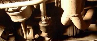
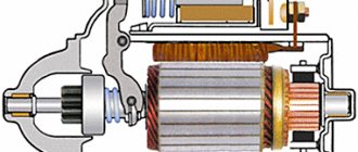
- Serviceability of blocks and main mechanisms. It is necessary to carry out diagnostics of vehicle devices in a timely manner. The VAZ 2114 starter fuse often fails when there is damage to the electric motor or the retractor element touching the body.
Fuse box repair
Before removing the VAZ 2114 mounting block, you should completely de-energize the car by removing the terminals from its battery.
After this you need:
- Find a common block.
- Detach it by opening the plastic latches.
- Dismantle the block and carefully inspect it.
If oxides are found on the relay contacts, on the fuse sockets, or on the fuses themselves, they should be carefully removed using a soft brush (bristles or brass). It is not recommended to use brushes made of hard material for cleaning.
Dismantled VAZ 2114 fuse box
Having removed the deposits, you should inspect the board itself - if there are any breaks in the tracks or unsoldered contacts on it, then they need to be soldered using a soldering iron, and then covered with dielectric electrical varnish (such as Tsapon-Lak or similar).
After all external defects have been removed, the mounting block should be installed in place (where it must be secured using the same latches) and the functionality of all electrical devices of the car should be checked. If after this it turns out that not all devices turn on, then you should look for the problem in the fuses.