Replacing the exhaust manifold and gasket
When dismantling the manifold, the gasket is destroyed in almost any case.
Therefore, it is worth removing its remains from the parts. Replacing the Kalina exhaust manifold gasket is a simple process. The use of sealants and other third-party substances is not recommended. They may later get into the crankcase. Replacing the manifold itself is simple - just take a new part and install it according to the principle in which it was attached. Assembling the system is simply the reverse order of the steps outlined in the last section.
Advice! Don't forget about cleanliness. This is an important factor in long and trouble-free operation of the car.
The standard intake manifold of the VAZ 2106 is designed to direct the air-gasoline mixture into the engine cylinders
Additionally, with the help of this important component in the vehicle system, fuel supply is heated, because when the combustible mixture is discharged, a reaction occurs with the release of cold
Replacing the exhaust manifold gasket and pipeline of a VAZ 2107
December 28, 2011
We install the gasket of the exhaust manifold and pipeline of a VAZ 2107 on a carburetor engine in case of its breakdown, which is usually accompanied by the appearance of characteristic noise of exhaust gases under the manifold.
For repairs you will need a standard set of tools. Before starting the disassembly process, it is worth carrying out a number of preparatory work, namely: we need to drain the cooling system and disconnect the battery. The procedure for removing the exhaust manifold and fuel wire is as follows:
- We remove the air filter housing from the studs, having first disassembled it and unscrewed the four nuts securing it to the carburetor.
- It is necessary to remove the exhaust pipe from the exhaust manifold studs by unscrewing the nuts securing it.
- It is necessary to disconnect all the drive elements of the throttle and air damper from the carburetor. We also disconnect the fuel hose, the hose of the vacuum ignition timing corrector and the block from the solenoid valve. Perhaps there is something else, we will also dismantle it.
- We remove the air intake by unscrewing its lower and upper mounting nuts, using a thirteen socket wrench.
- Remove the heat shield from the starter by also unscrewing the nut securing it.
- Disconnect the ground wire from the exhaust manifold and remove it from the stud. Not all versions have a ground wire on the manifold; sometimes it goes to the gearbox.
- Under the manifold, near the thermostat bypass pipe, you need to unscrew the two nuts securing the coolant supply tube to the pump. Ten nuts.
- Unscrew the seven nuts securing the intake and exhaust manifolds, remove the nuts and washers. Then, with peace of mind, we first remove the intake assembly with the carburetor, and then the exhaust. We remove the gaskets for which this repair was carried out.
This completes the dismantling work. Replace the gaskets and reassemble in reverse order. During assembly, lubricate all threaded connections with graphite lubricant, which is resistant to high temperatures. At this point, the repairs to replace the exhaust manifold gasket and intake pipe of the VAZ 2107 carburetor engine are completed.
remont-vaz2106.ru
Changing the manifold gasket
You may find that the gasket is stuck to the block, in which case you need to pry it off with a knife or a thin screwdriver and remove it from its seating location.
After which a rather unpleasant picture is revealed to us.
We remove the remnants of the old gasket on the surface of the cylinder block using a special spray, apply it to the entire area and wait about twenty minutes.
If traces remain, then remove with a thin blade. You can also put the surface in order using a zero.
After completing the procedures, we proceed to install the gasket, carefully put it on the studs and install the collectors in the reverse order.
The price of the VAZ 2109 exhaust manifold is about 1500-1700 rubles.
Tuning
1. Align the length of the channels.
2. A cavity appears under the carburetor, in which the mixture is mixed before entering the intake channels, regardless of which chamber the throttling occurs on.
The matching of the carburetor windows and the intake manifold is also of great importance; intake manifold and head. The mixture moves in the channels at high speed and the steps at the junctions form powerful vortex flows, increasing aerodynamic losses and preventing the mixture from entering the cylinders. By removing the steps at the interface between the carburetor and the intake manifold; intake manifold and head, as well as polishing the manifold and the internal cavities of the head to a mirror shine - we expand the range of torque and maximum power, and the higher the speed, the more pronounced the result.
The uniform distribution of the air-fuel mixture across the cylinders largely depends on the intake manifold. Many people believe that internal polishing of the manifold reduces intake losses. But this operation in itself is a torn page from a big book and cannot radically change anything. The uneven distribution of the mixture among the cylinders is primarily due to design errors in the design of manifolds. Different lengths of the intake tract lead to uneven filling of the cylinders, and the power balance among the cylinders changes depending on which carburetor damper is open. Quite primitive (for the intake manifold of a rear-wheel drive VAZ) It looks like this: when throttling on chamber 1, as well as when the carburetor is idling, cylinders 1 and 4 operate on a richer mixture than cylinders 2 and 3. When throttling at 2 in the th chamber (max load mode), a more enriched mixture enters 2 - 3 cylinders; and 1 and 4 experience air “hunger” for fuel. The reason for this pulsation of the mixture through the cylinders is the poor placement of the carburetor flaps above the intake manifold. By removing part of the partitions between adjacent channels, we kill 2 birds with one stone:
1. Align the length of the channels.
2. A cavity appears under the carburetor, in which the mixture is mixed before entering the intake channels, regardless of which chamber the throttling occurs on.
The matching of the carburetor windows and the intake manifold is also of great importance; intake manifold and head. The mixture moves in the channels at high speed and the steps at the junctions form powerful vortex flows, increasing aerodynamic losses and preventing the mixture from entering the cylinders. By removing the steps at the interface between the carburetor and the intake manifold; intake manifold and head, as well as polishing the manifold and the internal cavities of the head to a mirror shine - we expand the range of torque and maximum power, and the higher the speed, the more pronounced the result.
The step between the textolite gasket and the intake manifold, characteristic of most factory manifolds, creates additional resistance to flow in the intake tract.
Another way to optimize mixture formation on a stock manifold is to twist the air-fuel mixture in the large diffusers of the carburetor, and then continue this twist in the intake manifold channels. Various primitive devices periodically appear on the market, for example homogenizers (in the jargon “turbines”), which are mounted under the carburetor and supposedly improve the mixture formation process. The mixture is indeed slightly twisted, but the homogenizer itself blocks the cross-section of the inlet channel and is a significant obstacle to the flow. So there is more harm from such twisting. It is technically much more difficult to twist the mixture without blocking, and in some cases even increasing the cross-section of the inlet channels, but it is actually feasible. This is our “secret weapon” and a topic for another conversation.
On sports cars, until injection became firmly established on them, a different scheme was used - installing several carburetors. It gives a significant increase in torque and stretches it across the entire range - from low to maximum speed, and also increases maximum power. But the general laws of working with collectors outlined above also apply here. And with the complex application of all techniques, the results are brilliant.
Removing and installing the exhaust manifold
Typically, the exhaust manifold is removed when repairing the cylinder head or disassembling the engine. It is quite problematic to remove it, since before this it is necessary to perform the following procedures:
- Removing the air filter with housing and carburetor
- Removing the exhaust manifold
- Removing the “pants” (reception pipe)
After all these operations are completed, we can begin work, where we will need the following tools:
- Ratchet handle
- Extension
- Head for 13
- Open-end wrench 13
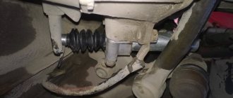
So, first you need to unscrew the nut securing the clamp that holds the coolant tube leading to the heater on the left side of the engine:
Then move the handset to the side so that it does not interfere with us in the future:
Now from the same side you can unscrew the fastening of the exhaust manifold to the cylinder head:
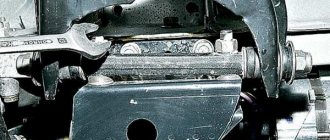
And also unscrew the nut on the right side of the manifold, as shown in the photo below:
Since there are no other fasteners, you can remove the manifold from the studs by slightly pulling it towards you:
And finally remove it from the engine compartment:
If the exhaust manifold of your VAZ 2106 needs to be replaced, then install it in the reverse order. The price of the new part is about 950 rubles, and it is made of cast iron, in contrast to the aluminum intake.
vaz2106-remont.ru
Removing and installing the intake manifold
The VAZ 2106 intake manifold itself is not difficult to remove, but before doing this, you will first have to perform the following procedures:
- Pliers
- head 13, regular and deep
- crank and ratchet handle
- extension cords
Now the only thing left to do is to pull the collector body with a certain amount of force and remove it from the studs. This operation is clearly demonstrated below:
How to check the vacuum booster
If the symptoms listed above occur, the vacuum unit must be checked. You can determine the functionality of the device without removing it from the car. For diagnostics, we need a rubber bulb from a hydrometer and a screwdriver (slotted or Phillips, depending on the type of clamps).
We carry out verification work in the following order:
- Turn on the parking brake.
- We sit in the cabin and press the brake pedal 5-6 times without starting the engine. On the last press, leave the pedal in the middle of its travel.
- We take our foot off the pedal and start the power plant. When the “vacuum” is working, the pedal will move down a short distance.
- If this does not happen, turn off the engine and move on to the engine compartment. We find the amplifier housing there, inspect the check valve flange and the end of the connecting hose. If they have visible breaks or cracks, we prepare to replace the damaged parts.
Dismantling
There is only one difficulty in this process - the inaccessibility of some fasteners. It is best to carry out this “operation” in a viewing hole or on a lift. Of course, this is not necessary, but it is much more convenient.
Work order:
- First you need to remove the negative terminal from the battery or turn off the mains switch.
- Next, it is recommended to drain all the antifreeze into a container prepared in advance.
- Next, you need to disconnect the fuel pipes. If the coolant is not drained, at this stage it will go into the cylinders.
- Now you have to find the throttle position and idle speed sensors, and then remove the wires from them.
How to properly insert fittings into the intake manifold?
Hi all. Today at the HBO shop I decided to raise the issue of inserting fittings into the intake manifold. As it turns out, many installers do not know how to properly make a tie-in, and as a result, many have problems during operation.
With these problems, they turn to more qualified specialists, who note a violation of the rules for installing fittings in the intake manifolds. As it turned out, a lot depends on the correct insertion and location of the fittings, first of all, mixture formation. Incorrect formation of a combustible mixture most often manifests itself as follows: the engine shakes when running on gas, popping noises (“sneezing”) are heard, etc.
Some LPG installers, when clients contact them with the question: “What is happening and why is the machine behaving this way?” - they answer differently. Sometimes they blame bad gas, sometimes they criticize low-quality gas equipment, there are also those who simply say that the engine is gasoline and is not designed to run on gas, so they “sausage” it slightly. In general, as you understand, you can justify anything if you want; you can “pin” a lot of things on a gullible client. However, after several days or months of torment (depending on how much patience), the deceived and perplexed car owner turns to professionals who, after a little diagnostics, conclude that the LPG was installed in violation of the rules for installing fittings in the intake manifolds.
Types of intake manifolds
There are the following types of intake manifolds:
- steel;
- aluminum;
- plastic;
- with variable geometry;
- with exhaust gas control valves (EGR);
- turbocharged;
- with point fuel injection, etc.
On modern engines, manifolds with point fuel injection are quite common. In this modification, fuel is supplied using electromagnetic injectors installed in each of its pipe-channels.
Schematic diagram of an intake manifold with point fuel injection
The intake manifold, like the engine as a whole, operates productively within a certain speed range. The design and type of installed manifold depends on the layout of the cylinder block, on the target orientation of the engine and on design solutions in general.
Payment via PayPal
After selecting payment via PayPal, the PayPal payment system will launch, where you need to select the payment method: bank card or PayPal account.
If you already have a PayPal account, then you need to log into it and make a payment.
If you do not have a PayPal account and you want to pay using a bank card via PayPal, you need to click on the “Create an Account” button - shown with an arrow in the picture.
PayPal will then prompt you to select your country and provide your credit card information.
After specifying the information required to make the payment, you must click on the “Pay Now” button.
Changing the manifold gasket
You may find that the gasket is stuck to the block, in which case you need to pry it off with a knife or a thin screwdriver and remove it from its seating location.
After which a rather unpleasant picture is revealed to us.
We remove the remnants of the old gasket on the surface of the cylinder block using a special spray, apply it to the entire area and wait about twenty minutes.
If traces remain, then remove with a thin blade. You can also put the surface in order using a zero.
After completing the procedures, we proceed to install the gasket, carefully put it on the studs and install the collectors in the reverse order.
The price of the VAZ 2109 exhaust manifold is about 1500-1700 rubles.
Tuning
1. Align the length of the channels.
2. A cavity appears under the carburetor, in which the mixture is mixed before entering the intake channels, regardless of which chamber the throttling occurs on.
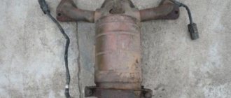
Removing the exhaust manifold of a VAZ 2106
Remove the corrugated hose from the heated air intake pipe.
After loosening the brake booster hose clamp, remove the hose from the intake pipe fitting.
Also, having loosened the fastening clamp, disconnect the coolant drain hose from the inlet pipe fitting.
We remove the vacuum supply tube to the electro-pneumatic valve of the EPHH system from the fitting of the intake pipe.
Using a 13mm spanner, unscrew the nut securing the front engine eye.
Using a 13mm wrench, unscrew the nut of the upper fastening of the heated air intake.
. and the lower fastening nut.
Remove the heated air intake.
Using a 13mm socket with an extension, unscrew the five common nuts securing the intake pipe and exhaust manifold.
Remove the intake pipe from the cylinder head studs.
Using a 13mm wrench, unscrew the two nuts securing the starter heat shield to the exhaust manifold.
. and with a “10” wrench - the bolt securing the screen to the bracket of the right support of the power unit.
Remove the heat shield.
Using a 13mm wrench, unscrew the two outer fastening nuts (one on each side) of the exhaust manifold.
Using pliers, remove the bracket for fastening the heater radiator outlet pipe from the exhaust manifold.
Remove the exhaust manifold.
. and the sealing gasket of the intake pipe and exhaust manifold (it consists of two parts).
Before installing the exhaust manifold and intake pipe, clean their flat surfaces, as well as the flat surface of the cylinder head, from carbon deposits and remnants of the old gasket. Lubricate the new gasket with a thin layer of sealant in the area of the holes for the cooling system channels and install the removed parts in the reverse order. Apply graphite lubricant to the threads of the studs.
2126.ru
How to install the fitting into the manifold correctly?
The insertion of the fitting into the manifold must be made strictly perpendicular to the flow of air passing inside the manifold. If this is not possible, the fitting must be inserted into the manifold at a certain angle. The angle should be such that the gas coming from the fitting is easily picked up by the air flow. It is unacceptable to insert fittings against the air flow; such a violation will lead to obstruction of gas flow inside the fitting.
Centering is also important. The fitting that cuts into the channel should be directed strictly to the center, or as close to it as possible. The fitting must not be placed on the side or somewhere towards the collector wall. The central location contributes to effective mixture formation, the gas is perfectly dispersed with air, resulting in a good combustible mixture with high efficiency. If the shape of the collector is not round, but, for example, square or rectangular, it is necessary to install the fitting so that it “looks” at the center, and the gas fuel is effectively mixed with the air flow.
In the case of a bifurcated collector, the insertion must be made before or after the bifurcation; in this case, two fittings are installed.
Removing the intake and exhaust manifolds of the VAZ-2106 engine
Removing the intake and exhaust manifolds
EXECUTION ORDER
Drain the coolant from a cold engine. For ease of operation, remove the air filter housing. Loosen the clamp of the coolant drain hose from the intake manifold...... and remove the hose. Loosen the clamp securing the vacuum brake booster hose...... and remove the hose. Using a 13-inch socket, unscrew the nut securing the negative wire and remove it. Using the “13” socket, unscrew the nut securing the eye and remove the eye. Having previously removed the hose from the warm air intake, use the “13” wrench to loosen the lower nut securing the air intake......and unscrew the upper nut securing the air intake. Using the “13” socket, unscrew the five common fastening nuts intake and exhaust manifolds to the cylinder head. Remove the intake manifold. Using a “13” wrench, unscrew the two nuts securing the starter heat shield to the exhaust manifold and remove the shield.
Using a 10mm wrench, unscrew the bolt securing the shield to the right engine mount bracket. Remove the shield. Disconnect the bracket securing the exhaust pipe to the gearbox. We disconnect the exhaust pipe from the exhaust manifold. Using a “13” wrench, we unscrew the two nuts securing the exhaust manifold to the cylinder head. Using pliers, we bend the ear of the bracket for the coolant drain pipe from the heater radiator from the manifold stud. We remove the exhaust manifold.
We install the manifold in the reverse order. Before installation, apply a thin layer of sealant to both intake manifold gaskets in the area of the coolant holes.
HdSxozARNdCZoZ0rmlIZmTSTN29TNdkrbraqebaqo3I5Ndk9etIUo3AwmLs6nl5wnl5SFlEwN2GVh4OUMDIuhRk4gDA4h3QSnlOuOBu0gBAypbefebaqebAsmLIQFlCsFlGwnlKxOB0rm2cWoDKrF JcZgBk2hJgZgBm4GJszhBarbraqebaqMdC0mj1QMb1ZNd90HjeZhBi4hBq0gZg4eR48F2SxoZ4=
avtolyubiteli.com
Replacing the gaskets of the intake and exhaust manifolds of a VAZ 2106 Zhiguli
- Repair manuals
- Repair manual for VAZ 2106 (Zhiguli) 1976-2005.
- Replacing intake and exhaust manifold gaskets
↓ Comments ↓
1. General information
1.0 General information 1.1 Safety precautions
2. Diagnosis of faults
2.0 Diagnostics of faults 2.1 diagnostics of faults in the engine and its systems 2.2 Diagnostics of faults in the clutch 2.3 diagnostics of faults in the gearbox 2.4 Diagnostics of faults in the driveline, rear axle, chassis, steering and braking system 2.5 Diagnosis of faults in the body 2.6. Diagnosis of electrical equipment faults
3. Engine
3.0 Engine 3.1 Cylinder head and timing mechanism 3.2 Lubrication system 3.3 Oil change 3.4 Replacing the camshaft drive chain guide 3.5 Replacing the camshaft and valve levers 3.6 Replacing the valve stem seals 3.7 Replacing the intake and exhaust manifold gaskets 3.8 Replacing the cylinder head gasket ov 3.9 Disassembling the head cylinder block, valve grinding
4. Engine power system
4.0 Engine power system 4.1 Replacing the air filter element 4.2 Replacing the fuel pump 4.3 Repairing the fuel pump 4.4 Replacing the fuel tank and its hatch cover
5. Carburetor
5.0 General information about the carburetor 5.1 Cleaning the fuel filter 5.2 Replacing the idle air system solenoid valve 5.3. Adjusting the carburetor 5.4 Replacing the carburetor 5.5. Carburetor repair
6. Engine cooling system
6.0 Engine cooling system 6.1 Replacing the coolant 6.2 Replacing the coolant pump 6.3. Replacing the thermostat 6.4 Replacing the engine radiator
7. Exhaust system
7.0 Exhaust system 7.1 Replacing exhaust system parts
8. Clutch
8.0 Clutch 8.1 Replacing fluid and bleeding the clutch hydraulic drive 8.2 Adjusting the drive 8.3 Replacing the clutch master cylinder 8.4 Repairing the clutch master cylinder 8.5 Replacing the clutch slave cylinder 8.6 Replacing the pressure plate assembly and clutch release bearing
9. Gearbox
9.0 Gearbox 9.1 Checking the level and changing the oil in the gearbox 9.2 Replacing the reverse light switch 9.3 Replacing the secondary shaft cuff 9.4 Replacing the gearbox 9.5 Repairing the gearbox 9.6 Replacing the speedometer drive 9.7 Features of repairing a five-speed gearbox
10. Cardan transmission
10.0 Cardan transmission 10.1. Maintenance 10.2. Replacing the driveshaft
11. Rear axle
11.0 Rear axle 11.1 Checking the serviceability of the rear axle 11.2 Changing the oil 11.3 Replacing the axle shaft and its cuff 11.4 Removing and installing the rear axle 11.5 Replacing the cuff of the drive gear 11.6 Replacing the gearbox 11.7 Repairing the gearbox
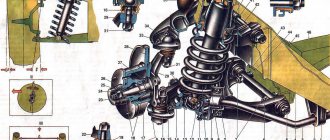
12. Front suspension
12.0 Front suspension 12.1. Maintenance 12.2 Replacing the bearings and hub cuff 12.3 Replacing the cushions and stabilizer bar 12.4 Replacing the ball joints 12.5 Replacing the shock absorbers 12.6 Replacing the springs 12.7 Replacing the upper arms and their rubber-metal hinges 12.8 Replacing the rubber-metal joints of the lower arms on a car 12.9 Replacing the lower arms 12.12 . Adjusting wheel alignment angles
13. Rear suspension
13.0 Rear suspension 13.1 Checking technical condition 13.2. Replacement of rear suspension parts
14. Steering
14.0 Steering 14.1 Adding oil 14.2 Checking the condition of the steering 14.3 Adjusting the gear engagement 14.4 Replacing steering rods 14.5 Replacing and repairing the pendulum arm 14.6 Removing and installing the steering wheel 14.7 Removing and installing the steering shaft 14.8 Removing and installing the steering mechanism 14.9 Removing the bipod
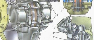
15. Brake system
15.0 Brake system 15.1 Checking the condition of the hydraulic drive 15.2 Checking the vacuum brake booster 15.3 Checking the functionality of the pressure regulator 15.4 Replacing brake fluid and bleeding the brake system 15.5 Replacing the brake pads of the front wheels 15.6 Replacing the brake pads of the rear wheels 15.7 Replacing the brake caliper of the front wheel 15.8 Replacing the brake cylinders of the front wheels 15 .9 Repair of front wheel brake cylinders
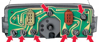
16. General information
16.0 General information 16.1. Checking electrical circuits 16.2 Fuse blocks 16.3 Replacing fuses 16.4 Replacing the main and additional fuse blocks 16.5. Replacing the relay 16.6 Replacing the ignition switch 16.7 Replacing the contact part of the ignition switch 16.8 Battery 16.9. Generator 16.10. Starter 16.11. Ignition system 16.12. Lighting, light and sound alarms 16.13. Windshield cleaner and washer 16.14. Repair of the electric heater motor 16.15. Control devices
17. Body
17.0 Body 17.1 Replacing the front bumper 17.2 Replacing the radiator grille 17.3 Replacing the hood latch 17.4 Replacing the hood 17.5 Replacing the windshield 17.6 Replacing the interior rear view mirror 17.7 Replacing the sun visor 17.8 Replacing the headliner 17.9 Replacing the ceiling grab handle
18. Heating and ventilation system
18.0 Heating and ventilation system 18.1 Replacing the electric heater fan 18.2 Replacing the heater radiator 18.3 Replacing the radiator casing 18.4 Replacing the heater valve
19. Car body care
19.0 Car body care 19.1 Car washing 19.2 Preservation and protection of paintwork
20. Applications
20.0 Applications 20.1 Tools used in addition to the standard set 20.2 Electrical diagram of VAZ-2106, VAZ-21061, VAZ-21063 cars produced in 1976–1987. 20.4 Tightening torques for threaded connections 20.5 Basic data for adjustments and monitoring 20.6 Characteristics of spark plugs 20.7 Fuel, lubricants and operating fluids used 20.8 Lamps used on the vehicle 20.9 Lip seals (oil seals)
| EXECUTION ORDER |
Adjustment and repair of the unit after checking the vacuum brake booster
In general, adjusting the VUT comes down to adjusting the free play of the brake pedal. To set it correctly, you need to adjust the length of the rod. The adjustment bolt controls the gap/protrusion. Correctly adjusting the position of the bolt itself will allow you to set the ideal timing of the valves.
When the leak test is completed, do not forget to adjust the free play of the brake pedal. Adjusting the rod length creates a gap that determines the amount of pressure on the brake cylinder
Therefore, it is very important to set the rod length correctly and set the appropriate gap. The free play of the pedal when the engine is not running should be from five to fourteen millimeters
This gap is controlled by a bolt located above the plane of the vacuum brake booster. A small gap leads to jamming of the working cylinder, resulting in rapid wear of the pads and increased fuel consumption of the car. In addition, the car begins to slow down randomly, as if you were driving with a handbrake. A large gap, on the contrary, leads to an increase in pedal travel, which indicates a violation of the tightness in the assembly
The free play of the pedal when the engine is not running should be from five to fourteen millimeters. This gap is controlled by a bolt located above the plane of the vacuum brake booster. A small gap leads to jamming of the working cylinder, resulting in rapid wear of the pads and increased fuel consumption of the car. In addition, the car begins to slow down randomly, as if you were driving with a handbrake. A large gap, on the contrary, leads to an increase in pedal travel, which indicates a violation of the tightness in the assembly.
Above we described how to check the operation of the brake vacuum device and adjust its operation if necessary. Now let's say a few words about its repair.
To ensure your own safety if your amplifier breaks down, take immediate action to repair or replace it. And if you can replace vacuum hoses in gasoline cars or pumps in diesel cars yourself, without resorting to the services of a car service, then it is recommended to entrust more serious work to professionals.
Of course, it costs some money, but when your own safety is at stake, it is better not to skimp. Contact the specialists. They will not only carry out the inspection competently, but also perform all the necessary work efficiently and with a guarantee.
It should be noted that after repair, it is important to synchronize the wheels when braking and check the ABS/ESP system. This requires a diagnostic stand and specialized equipment.
There are times when it is more expensive to repair a vacuum cleaner than to purchase a used amplifier that is in good condition. Therefore, it is recommended to look for the device at a disassembly site if necessary.
If you feel confident in your own abilities and, after checking, decide to repair the faulty vacuum booster yourself, then proceed as follows.
To begin, remove all the upholstery in the engine compartment and remove the windshield trim. Do not remove the tubes leading to the GTZ. This may allow air to enter the system.
Next, unscrew the cylinder from the vacuum booster and carefully tilt it forward to prevent deformation of the brake pipes. Before doing this, the vacuum transfer hose must be removed from the amplifier fitting
Carefully study the recommendations given by the manufacturer and proceed to dismantling the amplifier. Unscrew the mounting bolts and disconnect the terminal of the wire going to the brake light.
Only then remove the pedal using a special tool. If you are well versed in the design of the car, you can cope with checking and repairing the VUT. However, it is better to first go online and find instructions with an amplifier circuit. This will significantly speed up the implementation of the task and increase your chances of success.
Removing and replacing the intake manifold
In case of damage, it is necessary to remove the VAZ 2106 intake manifold and replace it with a new product. For this purpose it is necessary:
Disconnect the vehicle from power by removing the wire from the negative terminal of the battery. Drain the antifreeze from the cooling system into a specially prepared container. Remove the air purification filter on cars of early production years, and in modern vehicles, also disconnect the air supply hose from the filter. Next, we carry out similar actions with the vacuum tube and the ventilation hose going to the crankcase from the air supply chamber
Having removed the fasteners, we dismantle this camera with the hose. Disconnect the fuel supply hose, while paying attention to stopping the flow of gasoline. Remove the throttle cable fastening bracket, the sealing ring and disconnect the cable from the throttle valve lever. We put marks on the antifreeze supply hoses from the body of the air damper of the automatic operating principle. We exclude the leakage of antifreeze from the removed cooler pipes. We put marks and disconnect the vacuum tubes from the front of the carburetor along with the electrical wires and the quarry ventilation hose (if any). We dismantle the fasteners and unscrew the brake booster vacuum hose from the intake manifold. On some modifications, it is necessary to remove the installed wiring from the connector block coming from the temperature sensor. We dismantle the fasteners of the generator device from above to the intake manifold of the “six”. On some modifications, it is necessary to disconnect and dismantle the crankcase ventilation hose from the aft part of the cylinder head. We visually inspect the disconnection of all components of the vehicle systems from the intake manifold and dismantle it.
Installation of the intake manifold is carried out in the reverse order of removing the product, taking into account the following features:
- When dismantling the carburetor device, the product is installed with a new gasket.
- When removing the mounting of the generator electric machine, the mounting of the fasteners is carried out before installing the intake manifold of the “six”.
- Its installation is carried out on a cylinder head with an updated seal, and fastening is carried out with a torque wrench with a fixed torque.
- Check the correctness of all connections.
- We fill in the coolant, install and adjust the throttle cable, and if the carburetor settings are violated, adjust the idle speed and carbon monoxide concentration.
- We connect the intake manifold cooling outlet hose from the system.
The necessary modifications to the intake manifold are carried out to ensure a more uniform flow of the gasoline-oxygen mixture through the cylinders of the power plant. The mixture of fuel and air “pulsates” in the cylinders due to incorrect placement of the carburetor valves above the intake manifold of the “six”. If some of the partitions on neighboring highways are removed, then the result is the elimination of design errors in standardizing the linear dimensions of highways. In addition, a volumetric space is formed under the carburetor device, where the diffusion of the fuel-air mixture occurs before distribution along the highways.
Another way to modify the intake manifold is to completely coaxially align the carburetor windows, ports and cylinder head. Obstacles in the form of steps at the joints of the products create strong air flows that prevent the correct flow of fuel aerosol into the engine cylinders, and the vehicle loses its aerodynamic properties. It is necessary to remove these internal elevations and polish the internal planes of the cylinder head and intake manifold, which will make it possible to increase the value of the torsional moment and the maximum dynamics of the car. At higher engine speeds the result will be more noticeable.
Basically, the exhaust manifold on a VAZ 2109 car has to be removed in order to change the gasket, since it often burns out; in the place where the gasket burned out, exhaust gases begin to escape and go directly under the hood. And the sound gets louder, which is not very pleasant. To remove the manifold on the nine, you first need to:
- Remove the air filter with housing
- Remove the carburetor.
- Remove the intake manifold
From the tools we will need a 13mm spanner, a 13mm deep socket, a ratchet, and an extension cord.
We unscrew the four nuts of the exhaust manifold, which are attached to the exhaust pipe, clearly shown in the picture.
We move the pants a little to the side, pulling them off the stiletto heels. Then we unscrew the three fastening nuts that remain. Because when removing the dust intake manifold, six nuts were unscrewed.
We remove the exhaust manifold of the VAZ 2109 from the studs; this should not cause you any problems.
Self-replacement of the intake manifold on a VAZ 2107
To be honest, in my practice I have never encountered such cases when the intake manifold of a VAZ 2107 needed to be replaced. Since the part is made of aluminum alloy, it is actually very reliable and lasts almost the entire life of the car. But this manual will help you if you are disassembling the engine, that is, it will clearly show the process of removing the manifold. Below is a list of the necessary tools you will need to complete this repair:
- Ratchet handle
- Socket heads for 13: regular and deep
- Small to medium extension cord
- Vorotok
Before you begin this procedure, you must first remove the carburetor. Once you have dealt with this, you can move on.
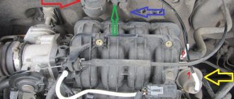
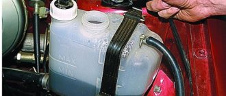
The first step is to disconnect two hoses: the coolant supply and from the vacuum brake booster, this is clearly shown in the photo below:
Now you can unscrew the two nuts securing the intake manifold from above, shown schematically in the photo below:
The most convenient way to do this is with a ratchet and a medium extension:
Then unscrew the three nuts from the bottom, which are visible in the picture below (the central one is not visible):
We also use a ratchet handle to do this quite quickly and conveniently:
After this, you can begin to remove the collector. Pull it slightly to the side and remove it from the studs:
If it is necessary to replace this part on a VAZ 2107, we buy a new one at a price of about 1,500 rubles (500 rubles for a used one) and install it in the reverse order.
Removing and replacing the intake manifold
In case of damage, it is necessary to remove the VAZ 2106 intake manifold and replace it with a new product. For this purpose it is necessary:
Disconnect the vehicle from power by removing the wire from the negative terminal of the battery. Drain the antifreeze from the cooling system into a specially prepared container. Remove the air purification filter on cars of early production years, and in modern vehicles, also disconnect the air supply hose from the filter. Next, we carry out similar actions with the vacuum tube and the ventilation hose going to the crankcase from the air supply chamber. Having removed the fasteners, we dismantle this camera with the hose. Disconnect the fuel supply hose, while paying attention to stopping the flow of gasoline. Remove the throttle cable fastening bracket, the sealing ring and disconnect the cable from the throttle valve lever. We put marks on the antifreeze supply hoses from the body of the air damper of the automatic operating principle. We exclude the leakage of antifreeze from the removed cooler pipes. We put marks and disconnect the vacuum tubes from the front of the carburetor along with the electrical wires and the quarry ventilation hose (if any). We dismantle the fasteners and unscrew the brake booster vacuum hose from the intake manifold. On some modifications, it is necessary to remove the installed wiring from the connector block coming from the temperature sensor. We dismantle the fasteners of the generator device from above to the intake manifold of the “six”. On some modifications, it is necessary to disconnect and dismantle the crankcase ventilation hose from the aft part of the cylinder head. We visually inspect the disconnection of all components of the vehicle systems from the intake manifold and dismantle it.
Installation of the intake manifold is carried out in the reverse order of removing the product, taking into account the following features:
When dismantling the carburetor device, the product is installed with a new gasket. When removing the mounting of the generator electric machine, the mounting of the fasteners is carried out before installing the intake manifold of the “six”. Its installation is carried out on a cylinder head with an updated seal, and fastening is carried out with a torque wrench with a fixed torque. Check the correctness of all connections. We fill in the coolant, install and adjust the throttle cable, and if the carburetor settings are violated, adjust the idle speed and carbon monoxide concentration. We connect the intake manifold cooling outlet hose from the system.
The necessary modifications to the intake manifold are carried out to ensure a more uniform flow of the gasoline-oxygen mixture through the cylinders of the power plant. The mixture of fuel and air “pulsates” in the cylinders due to incorrect placement of the carburetor valves above the intake manifold of the “six”. If some of the partitions on neighboring highways are removed, then the result is the elimination of design errors in standardizing the linear dimensions of highways. In addition, a volumetric space is formed under the carburetor device, where the diffusion of the fuel-air mixture occurs before distribution along the highways.
Another way to modify the intake manifold is to completely coaxially combine the carburetor windows, holes and cylinder head. Obstacles in the form of steps at the joints of the products create strong air flows that prevent the correct flow of fuel aerosol into the engine cylinders, and the vehicle loses its aerodynamic properties. It is necessary to remove these internal elevations and polish the internal planes of the cylinder head and intake manifold, which will make it possible to increase the value of the torsional moment and the maximum dynamics of the car. At higher engine speeds the result will be more noticeable.
Intake manifold VAZ 2106
Badboy
Group: Zhigulyonok Messages: 206 Registration: 21.3.2007 From: Moscow, VAO User No.: 10 Car: VAZ 21065 Color: White Year of Issue: 1998 Thanks said: 0 times
This work is performed to reduce the number of revolutions at which maximum torque is achieved and increase power at high speeds.
The most important thing is to mate the manifold (applies to both intake and exhaust) with the cylinder head. To do this, you need to paint the mating plane of the head with slow-drying paint (Kuzbaslak, for example) and lean the collector against it. Next, use a round file to select all the bright areas around the air channels on the manifold. Then wash off the paint from the head and commutator and repeat the procedure in reverse (paint the commutator, sharpen the head). You can limit yourself to one such cycle, but you can repeat it again for accuracy. An accuracy check can be done by painting both the manifold and the head and holding tracing paper between them. By holding the print to the light you can see all the inaccuracies.
The gasket is more difficult to deal with. You can't finish it with a file. You should use a drill or a round file clamped in a drill. The gasket is modified locally. The metal inserts in the gasket around the exhaust channels should not be touched.
Next is polishing. It makes sense to do it when overhauling the engine. To do this, the valves, rocker arm axle, rocker arms themselves, and camshaft are removed from the dismantled head. Then remove the manifold, take out the gasket and screw them back on.
Now there are two options:
The first is to take a cable 2-3 mm thick and apply a layer of coarse abrasive paste (such as GOI) on it and perform translational and rotational movements inside one of the channels (this is very long, hard and boring). Then, after visually checking the quality of the rough processing, a tarpaulin is tightly wrapped around the cable and lubricated with GOI paste. The procedure is repeated. This method does not guarantee maximum quality over the entire inner surface of the channel, but it does ensure that the most critical parts of the channel are treated.
The second method, which I have not tried but is very promising, is a sandblasting machine. Everything here is the same as in the first method, but instead of a cable, a jet of compressed air with abrasive particles is used
vaz-2106.ru
The standard intake manifold of the VAZ 2106 is designed to direct the air-gasoline mixture into the engine cylinders. Additionally, with the help of this important component in the vehicle system, fuel supply is heated, because When the flammable mixture is discharged, a reaction occurs with the release of cold.
The uniform distribution of the air-fuel mixture across the cylinders largely depends on the intake manifold. Many people believe that internal polishing of the manifold reduces intake losses. But this operation in itself is a torn page from a big book and cannot radically change anything. The uneven distribution of the mixture among the cylinders is primarily due to design errors in the design of manifolds. Different lengths of the intake tract lead to uneven filling of the cylinders, and the power balance among the cylinders changes depending on which carburetor damper is open. Quite primitive (for the intake manifold of a rear-wheel drive VAZ) It looks like this: when throttling on chamber 1, as well as when the carburetor is idling, cylinders 1 and 4 operate on a richer mixture than cylinders 2 and 3. When throttling at 2 in the th chamber (max load mode), a more enriched mixture enters 2 - 3 cylinders; and 1 and 4 experience air “hunger” for fuel. The reason for this pulsation of the mixture through the cylinders is the poor placement of the carburetor flaps above the intake manifold. By removing part of the partitions between adjacent channels, we kill 2 birds with one stone:
1. Align the length of the channels.
2. A cavity appears under the carburetor, in which the mixture is mixed before entering the intake channels, regardless of which chamber the throttling occurs on.
The matching of the carburetor windows and the intake manifold is also of great importance; intake manifold and head. The mixture moves in the channels at high speed and the steps at the junctions form powerful vortex flows, increasing aerodynamic losses and preventing the mixture from entering the cylinders. By removing the steps at the interface between the carburetor and the intake manifold; intake manifold and head, as well as polishing the manifold and the internal cavities of the head to a mirror shine - we expand the range of torque and maximum power, and the higher the speed, the more pronounced the result.
The step between the textolite gasket and the intake manifold, characteristic of most factory manifolds, creates additional resistance to flow in the intake tract.
Another way to optimize mixture formation on a stock manifold is to twist the air-fuel mixture in the large diffusers of the carburetor, and then continue this twist in the intake manifold channels. Various primitive devices periodically appear on the market, for example homogenizers (in the jargon “turbines”), which are mounted under the carburetor and supposedly improve the mixture formation process. The mixture is indeed slightly twisted, but the homogenizer itself blocks the cross-section of the inlet channel and is a significant obstacle to the flow. So there is more harm from such twisting. It is technically much more difficult to twist the mixture without blocking, and in some cases even increasing the cross-section of the inlet channels, but it is actually feasible. This is our “secret weapon” and a topic for another conversation.
On sports cars, until injection became firmly established on them, a different scheme was used - installing several carburetors. It gives a significant increase in torque and stretches it across the entire range - from low to maximum speed, and also increases maximum power. But the general laws of working with collectors outlined above also apply here. And with the complex application of all techniques, the results are brilliant.
Replacing the gasket
The work is performed on a cold engine.
Drain the coolant.
Loosen the fastening clamp and remove the coolant drain hose from the intake manifold,...
...remove the vacuum brake booster hose.
Using a 13mm wrench, unscrew the four copper-plated nuts securing the exhaust pipe to the exhaust manifold.
Using a 13mm wrench, unscrew the bolt securing the exhaust pipe to the gearbox and lower the exhaust pipe until it stops (see Replacing exhaust system parts).
Use a 13mm socket to unscrew the nut...
...and remove the negative wire and the eye from the stud.
Having previously removed the hose from the warm air intake, use the “13” key to unscrew the bottom...
...and the upper air intake nut.
Remove the coolant drain hose from the heater radiator from the outlet pipe.
Using a 13mm wrench, unscrew the second upper fastening nut...
...and use a 10mm wrench to secure the lower fastening bolt of the starter heat shield, and remove it (see Replacing the starter).
Using a 10mm wrench, unscrew the two nuts securing the pipe to the coolant pump...
...and remove it. A sealing gasket is installed between the pipe and the pump.
Using a 13mm socket, unscrew the seven nuts securing the manifold...
...and remove the intake...
...and exhaust manifolds.
Remove two gaskets from the studs.
We install the manifolds in the reverse order, replacing the gaskets with new ones and lubricating the threads of the studs with graphite lubricant. We attach the exhaust pipe of the muffler to the manifold with new brass nuts.
How to change
To perform this repair you will need the following tools:
Pliers head 13, regular and deep wrench and ratchet handle extensions
After the air filter, its housing and carburetor are removed from the car, you can proceed directly to the intake manifold. The first step is to remove the two hoses, which are shown in the picture below:
Now we unscrew the fastening of the air intake housing, which is screwed to the manifold on the left side:
Now you can unscrew the nuts securing the manifold to the cylinder head of the VAZ 2106. First, unscrew the two upper ones, which are located at the edges:
The most convenient way to do this is with a ratchet with a head:
And then unscrew the three nuts securing the intake manifold from below. Two are visible in the photo, and the third is in the center, but it is not visible.
Here you will need a long extension cord with a ratchet handle, otherwise you will have to suffer for a long time:
Then we finally remove it from the studs and remove it from the engine compartment:
If necessary, we replace this part. The price of a new manifold for the VAZ 2106 and other Zhiguli models of the classic family is around 1,500 rubles.
Installation proceeds in reverse order.
vz06-up.ru
See also:
Removing and replacing the intake manifold
In case of damage, it is necessary to remove the VAZ 2106 intake manifold and replace it with a new product. For this purpose it is necessary:
Disconnect the vehicle from power by removing the wire from the negative terminal of the battery. Drain the antifreeze from the cooling system into a specially prepared container. Remove the air purification filter on cars of early production years, and in modern vehicles, also disconnect the air supply hose from the filter. Next, we carry out similar actions with the vacuum tube and the ventilation hose going to the crankcase from the air supply chamber
Having removed the fasteners, we dismantle this camera with the hose. Disconnect the fuel supply hose, while paying attention to stopping the flow of gasoline. Remove the throttle cable fastening bracket, the sealing ring and disconnect the cable from the throttle valve lever. We put marks on the antifreeze supply hoses from the body of the air damper of the automatic operating principle. We exclude the leakage of antifreeze from the removed cooler pipes. We put marks and disconnect the vacuum tubes from the front of the carburetor along with the electrical wires and the quarry ventilation hose (if any). We dismantle the fasteners and unscrew the brake booster vacuum hose from the intake manifold. On some modifications, it is necessary to remove the installed wiring from the connector block coming from the temperature sensor. We dismantle the fasteners of the generator device from above to the intake manifold of the “six”. On some modifications, it is necessary to disconnect and dismantle the crankcase ventilation hose from the aft part of the cylinder head. We visually inspect the disconnection of all components of the vehicle systems from the intake manifold and dismantle it.
Intake manifold device
This intake manifold, a photo of which is posted on our Internet portal, is connected to pipes coming from the cooling system. When diagnosing the operation of this component of the engine starting system, it is necessary to monitor the tightness of the joints of these parts with the fittings of the manifold system and the wear of the clamps.
By its design, the VAZ 2106 intake manifold, the price of which is not exorbitant, but is within the acceptable range, is a fairly reliable mechanical unit and rarely fails. Among the identified defects, it is necessary to note the incorrect installation of such a part as the intake manifold gasket, which occurs due to incorrect installation of the spare part on the car either by the driver or by a car mechanic at a service station. It is rare, but it still happens that the intake manifold becomes corroded and excessive air supply appears, which, of course, requires replacing it with a new product.
A standard manifold can be purchased at all specialized VAZ auto parts stores. Let's look at the intake manifold, the design of which is very simple. It consists of an inlet pipe, a drain pipe and a fitting through which the coolant is discharged and cooled for normal operation of the vehicle.
Replacing the exhaust manifold and gasket
When dismantling the manifold, the gasket is destroyed in almost any case. Therefore, it is worth removing its remains from the parts. Replacing the Kalina exhaust manifold gasket is a simple process. The use of sealants and other third-party substances is not recommended. They may later get into the crankcase.
Replacing the manifold itself is simple - just take a new part and install it according to the principle in which it was attached. Assembling the system is simply the reverse order of the steps outlined in the last section.
Advice! Don't forget about cleanliness. This is an important factor in long and trouble-free operation of the car.
The standard intake manifold of the VAZ 2106 is designed to direct the air-gasoline mixture into the engine cylinders
Additionally, with the help of this important component in the vehicle system, fuel supply is heated, because when the combustible mixture is discharged, a reaction occurs with the release of cold
Installation of the injection system
After completing the preparation, you can begin installing the injector.
- First you need to install the cylinder head from the VAZ 21214 on the cylinder block.
- Then you need to install a new front block cover, a new crankshaft pulley and secure the DPKV.
- Place the gasket on the cylinder head intake and exhaust ports and screw the new intake and old exhaust manifolds into place.
- Place the spacer over the triangular mounting area where the 2 studs are located and a simple spacer over the manifold inlet ports.
- Insert the fuel rail with injectors into the exhaust pipes and secure it with 2 screws.
- Screw the receiver assembly with throttles and idle air control into its proper place.
- Secure the DD to the screw securing the distributor plug.
- Hook the speed sensor onto the speedometer drive gearbox.
- Attach the ignition module to the engine shield next to the brake reservoir.
- Secure the gas pedal to the right studs of the VUT.
- Attach the gas cable with one end to the pedal, the other end to the throttle assembly and secure it to the receiver bracket so that it sags slightly.
- Finally, you need to attach the fuel supply hose and the return hose to the injector.