02/23/2021 11,661 VAZ
Author: Ivan Baranov
To ensure normal engine starting in any weather, many different mechanisms and elements are used. But they are all combined into one system - the ignition system (I). We will tell you more about the SZ for the Oka car below. What functions does the Oka ignition coil perform, what malfunctions are typical for SZ in general, and how to set the advance angle - read below.
[Hide]
Ignition Features
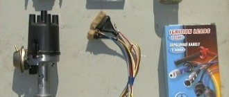
Diagram of a contactless SZ on the Oka
Before we talk about how to set and adjust the ignition on the Oka with your own hands in accordance with the diagram, let's understand the features of the SZ.
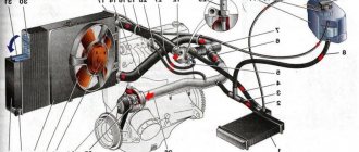
The ignition system on any car includes several different components, the main ones:
- Spark timing controller. This device is equipped with vacuum and centrifugal regulators. The device is designed to ensure the timing of spark formation, taking into account its standard installation, the number of engine revolutions, and the load on the motor. The signal reading procedure is based on the Hall effect.
- The switching device is designed to open the supply circuit of the primary winding of the short circuit, thus converting control signals into current pulses. When the ignition is activated, the connector of the switching device must not be disconnected under any circumstances, since this will lead to damage not only to this unit, but also to other elements of the SZ.
- Coil. In the ignition systems of Oka cars, in accordance with the diagram, a two-terminal short circuit with an open or closed magnetic circuit is used.
- Candles. This element is designed to transmit a high-voltage pulse, which contributes to the ignition of the combustible mixture in the cylinders of the internal combustion engine. The service life of spark plugs is about 10 thousand km, but this figure can be changed upward in accordance with the specifics of the spark plugs themselves. Or to a lesser extent, if for some reason the service life of the spark plugs is reduced.
- High-voltage cables designed to connect spark plugs to a distributor. In Oka, high-voltage circuits with distributed resistance are used. Do not touch them while the engine is running, as this may cause serious injury. It is also prohibited to start the power unit if the high-voltage circuit is broken (the wires may be broken or crushed, or the insulation on them may be damaged). If the insulation is broken, then other elements of the system may fail in accordance with the diagram.
- Egnition lock. According to the diagram, the lock is designed to start the engine by supplying voltage to an additional relay when the key is turned (video author - Nail Poroshin).
Typical system malfunctions
Among the malfunctions of the SZ, the following should be highlighted:
- Coil failure. This problem doesn't happen often, but it can happen nonetheless.
- Distributor failure. You can read more about distributor malfunctions, as well as troubleshooting, here.
- Spark plugs are worn out or have carbon deposits on them. This problem is relevant for many of our compatriots. Read about the reasons why soot appears and what ways to eliminate this problem exist in this article.
- Malfunction of high-voltage wires. The wires may be broken (broken) or their insulation may be damaged. Operating a car with such a problem is not allowed.
- Broken ignition switch. Wear on the inside of the lock will result in the driver being unable to start the engine with the existing key. Replacing the lock cylinder will solve the problem (the author of the video is Mikhail Burashnikov).
Tuning Oka ignition systems
has its own shortcomings, which can be eliminated with the help of modifications or tuning. Tuning Oka ignition systems
They also do not represent perfection, but the point is not in the design, but in the two-spark coil.
This coil is best installed on toy cars rather than production cars. A lot of methods were proposed that were supposed to make the coil more productive, they coated it with varnish and doused it with WD-40, but all in vain, this element of the car failed with enviable regularity. However, there is still an effective method. Its meaning is that this wonderful double-spark coil can be replaced with a pair of coils from a VAZ 2108. You will have to buy it in a store or rent it from a friend in the garage, and also pick up a switch from the same VAZ 2108 with the necessary connector, several meters of wires, better take with reserve, also good insulating tape and of course time. How long this will take depends on you, prepare in advance and the whole process will go by quickly, you won’t even have time to really notice. We start by unscrewing the old coil, you can send it to the village to your grandmother, it’s probably good for scaring geese in the pond, but it’s not suitable for giving a spark. We take new coils and screw them onto the right side member, the screws will hold them very well, there is no need to reinvent the wheel here. We fix both switches next to each other, you can even put them on the same stud, of course it’s good to tighten everything so as not to leave everything on the next bump.
Now let's start decommuting. The switches are connected in parallel, but the circuit contacts are approached separately; this point must be taken into account. Now, after such innovations, the spark power will become more powerful, old spark plugs are not suitable, we choose ones with a large spark gap, approximately 1.1 mm. It seems to be not at all difficult, but it’s surprising why many people still struggle with the factory coil. It is not at all necessary to take your cars to special centers where they will charge you money like for repairing a Formula car, all you need to do is replace the coil, you do not need to have a diploma as a qualified electrician. Tuning Oka
in the engine bay transformed it and took it to the next level. With the help of such simple movements and with minimal costs, you make the car quick and sharp.
Rate this article: Share with friends! Related posts:
checking the ignition coil of a VAZ 2108, VAZ 2109, VAZ 21099
replacing the ignition coil on a VAZ 2108, VAZ 2109, VAZ 21099
Diagnostics of engine malfunctions and its systems on VAZ 21213, 21214 (Niva)
Ignition installation instructions
How to set the lead angle correctly:
- First of all, you need to open the hood and remove the air filter. The angle diagnostic procedure should be carried out at idle engine speed, while the crankshaft should operate at a frequency of about 850-900 rpm. The angle itself can be deviated from TDC by no more than one degree. If it is set incorrectly, the motor may overheat, and the machine as a whole will not be able to develop the required power. Depending on the car, the problem may also cause detonation.
- To prevent the set ignition angle from leading to such consequences, you first need to align the mark on the flywheel of the internal combustion engine with the middle mark on the scale. The first mark is located on the flywheel itself, the second is on the scale of the crankshaft rear oil seal. At this moment, the piston in the cylinder will be located at TDC. When setting, keep in mind that each division corresponds to two degrees of the crankshaft gate.
- In addition, the ignition adjustment procedure can be carried out taking into account the marks located on the generator drive pulley and on the timing belt protective cover. The longest mark should correspond to the installation of the piston of cylinder 1 in the TDC position. As for the short mark, it corresponds to a five-degree advance of the crankshaft rotation.
- You need to disconnect the pipe connected to the vacuum regulator. Having done this, you can disconnect the high-voltage cable from the spark plug installed in cylinder 1. This wire will subsequently need to be connected to the strobe - before use, read the service book of the device.
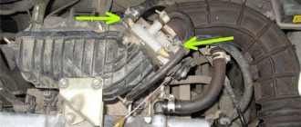
- After completing these steps, you need to remove the rubberized plug from the clutch housing hatch. The luminous flux should be directed into the crankcase hatch itself. If the angle is set correctly, the mark will be between marks 2 and 3.
- Next, using a wrench, you need to loosen the three nuts that secure the spark sensor. If you need to increase the torque, then the controller should be turned clockwise, respectively, if you decrease it, then counterclockwise. When the adjustment is complete, the nuts will need to be tightened.
SeAZ Oka Okula › Logbook › Adjusting the ignition and carburetor
There is no need to demand any intelligible traction from the Okula, this is not what this kart was created for, but nevermind, before the visit to the carburetor engineers, it was completely choking on gasoline, the idle speed was high, the ignition was late. Consumption was about 8 liters in the city and 6 on the highway.
I came to the service center, they removed the carb, blew it out/washed it, everything was displayed at face value on a special stand. After several years of inactivity, the carb was completely clogged.
Initially, on the gas analyzer at idle, the exhaust contained more than 6 units. CO, and adding gas, the value increased. After tuning at idle, CO was 3 units. and about 1 unit. when adding gas.
We set the ignition on the strobe light, it was late.
Now the engine is almost inaudible, the idle speed is smooth, and the dips in traction when adding speed have disappeared. I’ll go again in 3-4 days to check)
Design
The ignition system of the VAZ Oka consists of only seven main elements:
All elements are connected to each other by wiring.
Using the ignition switch, the driver controls the power supply to the system from a source - the battery, while the voltage passes through the auxiliary relay and fuses. The lock has three positions - “0”, in which all electrical consumers are turned off, “1” - voltage is supplied to the ignition system and a number of other devices, and “2” - current is supplied to the starter. This switching sequence ensures that the ignition system is activated at the moment the engine starts.
Spark torque sensor
The spark timing sensor is one of the main ignition components, since it sets pulses that are subsequently converted into a spark discharge between the spark plug contacts. This sensor is driven by the camshaft, which allows you to accurately set the timing of the spark in the cylinders.
The main working elements of the unit are the Hall sensor and a special screen with slots mounted on the drive shaft interacting with the camshaft. The interaction of these elements leads to the emergence of control impulses.
The sensor not only sets pulses, it also “adjusts” to the operating conditions of the motor, adjusting the advance angle depending on the operating conditions of the motor (speed, load).
The adjustment is carried out by two regulators - vacuum and centrifugal, included in the design of the spark generation moment sensor.
Until 1989, Oka used a sensor of type 55.3706, and after that it was replaced by model 5520.3706.
Switch
The switch acts as a circuit breaker for the primary winding of the coil, using control pulses coming from the spark sensor. Circuit interruption in the switch is performed by the output transistor. The switch is completely electronic, without any moving elements, so the ignition system is contactless.
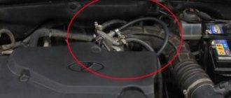
Several types of switches were installed on the VAZ-1111 and 11113 - 36.3734, 3620.3734, as well as HIM-52. The switch is installed in the engine compartment near the engine panel. It is secured with two bolts, so replacing the switch is quite simple.
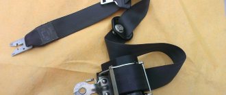
Coil
Oka received a two-terminal ignition coil, which made it possible to remove the distributor from the design.
It is noteworthy that the high voltage in this coil is supplied simultaneously to both spark plugs. Moreover, due to the offset strokes in the engine cylinders, only one spark discharge is working, the spark on the second spark plug is the so-called “idle”.
The standard coil on the Oka is type 29.3705, but it has an analogue that is suitable for use on a small car - 3012.3705.
Wires, spark plugs
All wiring consists of low and high voltage wires. The first ones are used to connect all the components up to the coil. These are ordinary wires of small cross-section, which is quite sufficient, since the voltage in the circuit up to the coil is low.
High voltage wires are used to connect the coil terminals to the spark plugs. For ease of connection, lugs are installed at the ends of these wires.
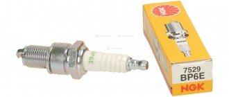
Recommended for use on Oka are spark plugs of type A17DVR - with an extended thread and an interference suppression resistor, as well as their analogues.
Setting the advance angle
Setting the ignition timing is the only operation that is performed in the ignition system.
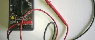
A strobe light is used to set the angle correctly. The technology for performing the work is not complicated. The algorithm of actions is as follows:
- We connect the strobe to the power source and the tip of the spark plug of the 1st cylinder (according to the instructions for the device);
- Remove the plug from the inspection window on the clutch housing;
- We start the engine (it should be idling);
- We direct the beam of light from the strobe into the viewing window;
- We determine the position of the marks (with the angle correctly set, the mark on the flywheel at the moment the strobe light beam flashes should be located between the central and rear marks on the crankcase);
- If the marks are not positioned correctly, make adjustments. To do this, loosen the bolts securing the spark moment sensor and rotating it around its axis until the marks match;
After adjustment, tighten the sensor fasteners, turn off the engine, disconnect the strobe light and replace the plug.
Common electrical faults
Common problems with electrical equipment on VAZ-1111 and 1113:
- Failure of external lighting devices. A common cause of failure is burnt out lamp filament; the unit must be replaced. If the light bulb is intact, then there may be a defect in the electrical wiring, due to which a short circuit occurs and the fuse fails. The fuse link is replaced with an identical one; it is prohibited to use parts designed for a higher current. It is also unacceptable to install homemade jumpers (“bugs”), as this can cause a fire. If a repeated burnout occurs, it is necessary to check the circuit and eliminate the wiring fault.
- Wire breaks occur at points where the insulation is subject to bending or friction against moving surfaces. An example of such a point is the junction of the door and the body. Damaged areas must be replaced with products made of similar material with an identical cross-section.
- Oxidation of contact surfaces due to moisture or aggressive liquids (for example, battery electrolyte). It is necessary to clean the surfaces down to metal, restoring the transmission of electric current.
- Relay failure associated with burnt contacts or coil breakage. The unit cannot be repaired; it must be replaced with a new one. In the event of a rapid re-failure, the vehicle's electrical system must be checked at a car service center.
- Sudden battery discharge is due to an internal short or current leakage. In winter, a partially charged battery may lose capacity due to low air temperatures. You need to charge the battery and check the condition of the wiring. If necessary, the power source must be replaced.
- Pulsating operation of external lighting lamps with an unusually bright glow indicates a breakdown of the relay regulator on the generator. Repair requires removing the unit and replacing failed components.
- Insufficient battery charge (the warning light does not go out when the engine is running). The cause may be wear on the brushes or commutator, or insufficient tension on the drive belt. The generator needs to be repaired, since the battery charge is enough for 150-200 km during the daytime.
- Poor contact between the ends of the cylindrical fuses and the spring-loaded elements in the mounting block. It arises due to the design features of the unit. Many owners, tired of dealing with the defect, install homemade blocks for knife inserts. Usually a short section from the GAZ-3110 is used, designed for 13 seats. There are self-assembled units designed for fuses and relays.
Electrical diagram of VAZ-1111 with symbols
List of elements indicated in the diagram:
- 1 — side turn signal repeater located on the front fender;
- 2 — front direction indicator;
- 3 — head lighting device;
- 4 - electric motor used to drive the radiator cooling impeller;
- 5 — warning sound signal (horn);
- 6 - temperature sensor, which ensures that the cooling system impeller is turned on;
- 7 — motor for driving the front window washer pump;
- 8 — distribution sensor of the ignition system;
- 9 — lead-acid battery;
- 10 - electric motor for starting the engine;
- 11 — ignition system controller;
- 12 — spark plugs installed in the cylinder head;
- 13 — ignition system coil;
- 14 — alternating current generator;
- 15 — liquid temperature indicator in the cooling jacket;
- 16 - control sensor that determines emergency oil pressure in the engine;
- 17 — connector for installing a portable lamp;
- 18 — windshield wiper operation controller;
- 19 — indicator sensor of the fluid level in the hydraulic brake drive system;
- 20 — brake pedal position limit switch;
- 21 — motor for driving the trapezium wipers on the front window;
- 22 - electromagnet located in the carburetor valve;
- 23 — limit switch responsible for the operation of the reverse gear signals;
- 24 — starter controller;
- 25 — headlight control relay (low beam);
- 26 - similar unit for high beam;
- 27 — controller of direction indicators and emergency lights;
- 28 — cigarette lighter socket;
- 29 — speed switch for the heating system motor;
- 30 - additional resistor that determines the rotation speed of the heater fan impeller;
- 31 — external lighting operating mode switch;
- 32 - fuse block;
- 33 — additional protective element for fog lamps;
- 34 — rear window heating control controller;
- 35 - start relay, necessary for the operation of the cooling system fan;
- 36 — control relay for the control indicator of the position of the parking brake lever;
- 37 — control of the rear window cleaning system (together with the washer);
- 38 — glass heating operating mode switch;
- 39 — rear fog light button;
- 40 — indicator of the open starting valve in the carburetor;
- 41 — alarm control button;
- 42 — ignition switch;
- 43 — distribution relay of the ignition system;
- 44 — heating fan impeller motor;
- 45 — indicator of the amount of gasoline in the tank;
- 46 — interior lighting switch located on the central pillar;
- 47 — instrument cluster;
- 48 — front wiper control;
- 49 — turning on the windshield washer;
- 50 — horn control button;
- 51 — lever for changing the operating modes of the head lighting;
- 52 — direction indicator control lever;
- 53 — limit switch, responsible for indicating the position of the parking brake lever;
- 54 — interior lighting lamp;
- 55 — limit switch located behind the carburetor choke control button;
- 56 — motor for driving the glass washer pump on the rear door;
- 57 — stern canopy;
- 58 - fog signal, located on the rear of the car;
- 59 — registration plate illumination system;
- 60 — tailgate glass heating threads;
- 61 — stern wiper blade drive motor.
The specified colors of connecting wires correspond to the factory documentation. During repairs, many owners replace sections of the harnesses with cables with insulation of a random color. Because of this, some vehicles have difficulty identifying the wiring.