When designing the small car VAZ Oka 1111 and 11113, many components and mechanisms were “borrowed” from other VAZ models, which made it possible to reduce the cost of car production and speed up the start of production. But the designers had to significantly rework some components in order to adapt them to the features of the Oka engine. One of these components is the ignition system.
When creating the ignition system, the designers used modern developments of those years. The VAZ Oka received a non-contact ignition system. At the same time, the features of the power plant made it possible to somewhat simplify the system and reduce the number of components, which had a positive impact on the reliability of this component of the power plant.
Design
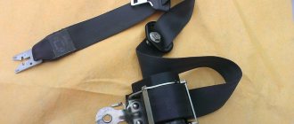
The ignition system of the VAZ Oka consists of only seven main elements:
- Auxiliary relay;
- Egnition lock;
- Circuit breakers;
- Switch;
- Spark moment sensor;
- Coil;
- Candles;
All elements are connected to each other by wiring.
Using the ignition switch, the driver controls the power supply to the system from a source - the battery, while the voltage passes through the auxiliary relay and fuses. The lock has three positions - “0”, in which all electrical consumers are turned off, “1” - voltage is supplied to the ignition system and a number of other devices, and “2” - current is supplied to the starter. This switching sequence ensures that the ignition system is activated at the moment the engine starts.
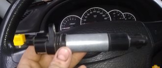
Spark torque sensor
The spark timing sensor is one of the main ignition components, since it sets pulses that are subsequently converted into a spark discharge between the spark plug contacts. This sensor is driven by the camshaft, which allows you to accurately set the timing of the spark in the cylinders.
The main working elements of the unit are the Hall sensor and a special screen with slots mounted on the drive shaft interacting with the camshaft. The interaction of these elements leads to the emergence of control impulses.
The sensor not only sets pulses, it also “adjusts” to the operating conditions of the motor, adjusting the advance angle depending on the operating conditions of the motor (speed, load).
The adjustment is carried out by two regulators - vacuum and centrifugal, included in the design of the spark generation moment sensor.
Until 1989, Oka used a sensor of type 55.3706, and after that it was replaced by model 5520.3706.
Switch
The switch acts as a circuit breaker for the primary winding of the coil, using control pulses coming from the spark sensor. Circuit interruption in the switch is performed by the output transistor. The switch is completely electronic, without any moving elements, so the ignition system is contactless.
Several types of switches were installed on the VAZ-1111 and 11113 - 36.3734, 3620.3734, as well as HIM-52. The switch is installed in the engine compartment near the engine panel. It is secured with two bolts, so replacing the switch is quite simple.
Coil
Oka received a two-terminal ignition coil, which made it possible to remove the distributor from the design.
It is noteworthy that the high voltage in this coil is supplied simultaneously to both spark plugs. Moreover, due to the offset strokes in the engine cylinders, only one spark discharge is working, the spark on the second spark plug is the so-called “idle”.
The standard coil on the Oka is type 29.3705, but it has an analogue that is suitable for use on a small car - 3012.3705.
Wires, spark plugs
All wiring consists of low and high voltage wires. The first ones are used to connect all the components up to the coil. These are ordinary wires of small cross-section, which is quite sufficient, since the voltage in the circuit up to the coil is low.
High voltage wires are used to connect the coil terminals to the spark plugs. For ease of connection, lugs are installed at the ends of these wires.
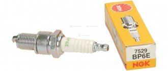
Recommended for use on Oka are spark plugs of type A17DVR - with an extended thread and an interference suppression resistor, as well as their analogues.
Checking and replacing spark plugs VAZ "OKA" 1111 1988-2008
- Repair manuals
- VAZ "OKA" 1111 1988-2008
- Checking and replacing spark plugs
| USEFUL TIPS Replace spark plugs every 30,000 km, even if they are still in working order: old spark plugs can increase fuel consumption. When preparing for winter use, replace the spark plugs with new ones. Regularly check the connections between the high-voltage wires and the spark plugs and ignition coil. Keep high-voltage wires clean by periodically wiping them with a cloth. Contamination on wire insulation can cause current leakage |
Use the following spark plugs:
A17DVRM, A17DVR or FE65CPR.
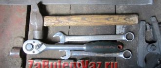
You will need: spark plug wrench, bit, round feeler gauge, spark plugs.
This is what a spark plug wrench with a bit looks like.
| 1. Disconnect the wire from the “–” terminal of the battery. |
| 2. Remove the tip from the spark plug. |
| WARNING When removing spark plugs, be careful - if the engine is hot, you may get burned. Do not pull on the wire. Apply force to the tip. |
| 3. Clean the spark plug and the area around it from dirt so that when turning the spark plug out, no dirt gets into the cylinder. |
| 4. Carefully move the spark plug with a wrench and then completely remove the spark plug by hand. |
| NOTE If the spark plug is hard to turn out after the first start due to carbon deposits, do not apply much force so as not to damage the threads in the cylinder head. Lightly twisting and unscrewing the candle, gradually turn it out of the head. |
| 5. Clean the electrodes with sandpaper. Examine the candle. If there are cracks on the insulator, the threads or electrodes are damaged, the spark plug must be replaced. Light brown carbon deposits, which evenly cover the lower part of the spark plug with a thin layer, do not affect the operation of the ignition system and do not need to be cleaned off. The absence of carbon deposits on the spark plug indicates either that the engine is running on a lean mixture, or that the ignition timing is incorrectly set, or that the spark plug brand does not match the engine type. A shiny black deposit indicates oil has entered the engine cylinder. Such a candle must be cleaned. |
| WARNING Do not sand the center electrode insulator skirt. Scratches on the skirt will increase carbon deposits. |
| 6. Check the gap between the spark plug electrodes (with a round feeler gauge only). The gap should be 0.7–0.8 mm. | 7. If the gap differs from the specified one, adjust it by bending the side electrode. |
| WARNING Adjust the gap only by bending the side electrode. Any bending of the center electrode will cause the spark plug insulator to break. To check the gap, use only a round feeler gauge. Over time, a groove will form on the side electrode, and measuring with a flat feeler gauge will give the wrong gap value. |
| 8. Tighten the spark plug tip if it is loose on the thread. | 9. Clean the oxidized contact in the tip of the high-voltage wire. If necessary, adjust the contact so that it fits snugly on the spark plug tip. |
| 10. Screw the spark plug into the cylinder block and tighten it with a wrench. Install the tip onto the spark plug until it stops. Check that it fits snugly. |
| WARNING To avoid damaging the threads in the cylinder head when installing spark plugs, first tighten them by hand, then tighten them with a standard spark plug wrench. Do not over-tighten the spark plugs; the ceramic plug insulator may crack, causing poor engine performance. |
↓ Comments ↓
VAZ-1111-11113 OKA
Section 1. VEHICLE STRUCTURE
General information about cars Vehicle registration data
Section 2. ENGINE
Possible engine malfunctions, their causes and solutions Useful tips Replacing the coolant Replacing the engine oil and oil filter Cleaning the crankcase ventilation system Setting the piston of the first cylinder to the TDC position of the compression stroke Adjusting the tension of the camshaft drive belt Replacing the tension roller Replacing the camshaft drive belt Removing, installation and troubleshooting of the flywheel Replacement of engine seal parts Cylinder head Adjustment of clearances in the valve drive Removal and installation of the engine Engine repair Lubrication system Cooling system Exhaust system Power supply system
Section 3. TRANSMISSION
Clutch Gearbox Front wheel drives
Section 4. CHASSIS
Front suspension Rear suspension
Section 5. STEERING
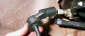
Inspection and check of the steering system on the vehicle Steering column Steering mechanism Steering linkage
Section 6.BRAKE SYSTEM
Checking and adjusting the brake system Replacing the brake fluid Bleeding the brake system hydraulic drive Master cylinder Brake vacuum booster Pressure regulator Replacing brake hydraulic hoses and pipelines Front wheel brakes Rear wheel brakes Parking brake
Section 7. ELECTRICAL EQUIPMENT
Fuses and relays Generator Starter Ignition system Lighting, light and sound alarms Windshield wipers and washers Engine cooling fan Instrument cluster Switches and switches
Section 8.BODY
Possible body malfunctions, their causes and solutions Replacement of buffers Hood Side door Rear door Rear view mirrors Seats Heater Body care
Applications
Appendix 1. Tightening torques for threaded connections Appendix 2. Fuels and lubricants and operating fluids Appendix 3. Basic data for adjustments and control Appendix 4. Filling volumes, l Appendix 5. Oil seals Appendix 6. Layout of rolling bearings Appendix 7. Car electrical diagram : 1 — side turn signal repeater; 2 — front direction indicator; 3 - headlight; 4 — electric motor of the cooling system fan; 5 — sound signal; 6 - sensor for turning on the electric motor
How it all works
The principle of operation of the ignition system is as follows: after turning the key to position “1” el. Energy from the battery is supplied to the ignition system components through the lock, fuses and auxiliary relay. In this case, high voltage pulses are not generated, since the spark torque sensor is not yet operational.
After activating the starter, the timing drive begins to rotate the camshaft, and accordingly the sensor shaft - the Hall sensor begins to interact with the screen, due to which control pulses are created.
Arriving at the commutator, these pulses interrupt the power supply circuit of the coil winding. When the power circuit is broken, a high voltage pulse is induced in the coil, which is transmitted through high-voltage wires to the spark plug, which leads to the formation of a spark between its electrodes.
Malfunctions
The simplified design of the ignition system and the absence of moving components ensures high reliability and ease of maintenance.
There are not so many malfunctions in the Oka ignition system:
- Switch failure;
- Hall sensor malfunction;
- Coil failure;
- Breakage or breakdown of wires, oxidation of contacts;
- Spark plug malfunction;
- Violation of the ignition timing;
Since the ignition system is directly involved in the operation of the engine, any malfunction in it immediately affects the performance of the engine - interruptions occur, the unit does not develop power, popping noises appear, or the unit simply does not start.
Diagnosis of a malfunction is carried out by visual inspection of the wiring and its connections, as well as by sequentially replacing all components with known good ones. A check using measuring instruments allows you to more accurately determine the faulty element.
The search for the problematic element is carried out from the candles. That is, first the presence of a spark is checked on them, then the high-voltage wires are inspected, and then the performance of the coil, switch, and Hall sensor is diagnosed.
The components of the ignition system are non-repairable, so if they break down they must be replaced.
Oka gap on spark plugs
Category: Maintenance
Vehicle characteristics: The dimensions of the car are as follows: length - 3046, width - 1100, height - 1929 mm. The wheelbase is 2168 mm. Ground clearance 192 mm. The car is equipped with a hybrid power unit. The 4-cylinder engine is equipped with a system that provides engine power output. There are 4 valves per cylinder. The diameter of one cylinder is 70 mm, the piston stroke is 78 mm. The engine crankshaft accelerates to 1000 rpm. Maximum torque is maintained up to 4000 rpm.
Posted by admin: at the request of Ferdinand
Watch the VIDEO about the spark plug gap of the VAZ 1111 Ok.
Review from a car owner named Henry: Acceleration and comfort, eats any domestic gasoline
Original name: . VAZ1111?
Release date: December 23, 2021
Laughter on the topic: What is the difference between alcohol consumption among Russians and the French: The French eat and drink, Russians drink and snack.
Replace spark plugs every 30,000 km, even if they are still in working order: old spark plugs can increase fuel consumption.
When preparing for winter use, replace the spark plugs with new ones.
Regularly check the connections between the high-voltage wires and the spark plugs and ignition coil. Keep high-voltage wires clean by periodically wiping them with a cloth. Contamination on wire insulation can cause current leakage
Use the following spark plugs:
A17DVRM, A17DVR or FE65CPR.
You will need: spark plug wrench, bit, round feeler gauge, spark plugs.
This is what a spark plug wrench with a bit looks like.
1. Disconnect the wire from the “–” terminal of the battery.
2. Remove the tip from the spark plug.
When removing spark plugs, be careful - if the engine is hot, you may get burned.
Do not pull on the wire. Apply force to the tip.
3. Clean the spark plug and the area around it from dirt so that when turning the spark plug out, no dirt gets into the cylinder.
4. Carefully move the spark plug with a wrench and then completely remove the spark plug by hand.
If the spark plug is difficult to turn out after the first start due to carbon deposits formed, do not apply much force so as not to damage the threads in the cylinder head. Lightly twisting and unscrewing the candle, gradually turn it out of the head.
Setting the advance angle
Setting the ignition timing is the only operation that is performed in the ignition system.
A strobe light is used to set the angle correctly. The technology for performing the work is not complicated. The algorithm of actions is as follows:
- We connect the strobe to the power source and the tip of the spark plug of the 1st cylinder (according to the instructions for the device);
- Remove the plug from the inspection window on the clutch housing;
- We start the engine (it should be idling);
- We direct the beam of light from the strobe into the viewing window;
- We determine the position of the marks (with the angle correctly set, the mark on the flywheel at the moment the strobe light beam flashes should be located between the central and rear marks on the crankcase);
- If the marks are not positioned correctly, make adjustments. To do this, loosen the bolts securing the spark moment sensor and rotating it around its axis until the marks match;
After adjustment, tighten the sensor fasteners, turn off the engine, disconnect the strobe light and replace the plug.