04/27/2021 6,829 VAZ 2115
Author: Ivan Baranov
Vehicle speed is the main parameter that every driver must monitor. Exceeding the permissible speed limit is not only fraught with a fine, but can also lead to serious consequences. Where is the VAZ 2115 speed sensor located, what malfunctions can occur in its operation, how to check and replace the controller - you will find answers to these questions in this article.
[Hide]
Speed sensor, device and principle of operation
The purpose of the speed controller in carburetor and injection engines is to transmit information about the vehicle's driving speed to the instrument panel. The principle of operation of the DS is quite simple and is based on the Hall effect:
- The controller transmits voltage signals to the ECU with a frequency directly proportional to the speed of rotation of the vehicle wheels.
- The ECU, in accordance with the signals received from the engine, adjusts the engine at idle speed and, using the XX sensor, controls the air supply bypassing the throttle.
- It is very important that the controller pulse frequency is directly proportional to the actual speed of movement.
Speedometer drive: types and differences
A speedometer is an important element in cars, as well as several other vehicles, as it is necessary to monitor speed in order not to violate traffic rules. But this is not the last function of this device.
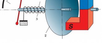
All possible speedometers have a high-speed magnetic unit; due to the rotation of the magnets, a flow is formed, it moves through the coil, thereby facilitating the induction of eddy currents. They thereby begin to create more magnetic fields. They interact with each other, the needle of the device moves along the frequency scale, with the help of this the magnet rotates.
All speedometers are divided into three categories.
- Mechanical speedometers.
- Electromechanical speedometers.
- Electronic speedometers.
Mechanical speedometers. In this type of speedometer, the process of speed measurement and indication occurs thanks to a mechanical device. A gear is used as sensors, which is connected to the secondary shaft of the gearbox; this is the speed unit with an arrow indicator and the drum counter. Previously, speedometers were used in the form of a drum and tape. But they stopped using them quite a long time ago.
Electromechanical speedometers. In these devices, speed is measured using various electronic or electromechanical sensors that are connected to the gearbox. The speed is indicated by a milliammeter or the speed unit of a mechanical speedometer, and the distance is indicated by a counting drum, which drives a stepper motor.
We recommend:
How to change gears correctly on a gearbox
Electronic speedometers. This is a development of new electromechanical speedometers; the main difference is the replacement of the odometer - in an electronic device it is completely digital.
Signs of a malfunction in the VAZ 2115 speed sensor
- One of the most likely symptoms of a breakdown is incorrect values on the speedometer, in particular, the dial needle moves chaotically in different directions.
- Another sign is that the engine runs intermittently at idle.
- The revs fluctuate at XX.
- Increased fuel consumption.
- Dips during acceleration, i.e. when the driver presses the gas, the engine does not react to this in any way, power does not gain.
Diagnostics of the speed sensor operation
Diagnostics of the sensor's performance is performed using two methods.
To implement the first method you will need a multimeter:
- First of all, dismantle the controller itself. Read removal instructions below.
- Next, set the tester to AC voltage measurement mode.
- Then the multimeter probes must be shorted to the contacts of the controller plug. Connect the first probe to the contact going to the dashboard, it is located in the center, and the other to the car body, i.e. to ground.
- There is a special rod in front of the controller. When it rotates, the device starts. To diagnose the operation of the regulator, it is necessary to rotate the rod, for which a metal tube of the same size is installed on it.
- The rod will begin to rotate, and the multimeter display will display information about the alternating voltage, or rather, its surges. Moreover, the higher the rod rotation speed, the larger the jumps in values. This will indicate a controller malfunction.
The second method of checking the device is carried out without dismantling, however, to do this you need to drive the car into a pit or overpass:
- When the car is in the pit, jack up the left front wheel.
- Next, find the controller and disconnect the connected wiring from it.
- Now take your multimeter. Its probes must be connected to the ground contact and the impulse transmission contact on the ECU; on the block this is the central and outermost contact.
- Then spin the jacked wheel and check the multimeter readings to see if any voltage surges are occurring. If you don’t have a tester, you can use a regular test lamp with wires connected to it. Connect the first wire to the power supply, that is, to the left contact, and the other to the central one. If the light source blinks when the wheel rotates, then the DS is working.
It is quite possible that the cause of the DC failure lies in poor contact with the vehicle’s electrical network; in this case, you simply need to replace or clean the contacts. Before diagnosing, inspect the device. If it shows signs of damage, there may be no point in even checking it.
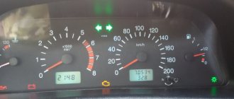
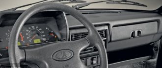
Designations of light bulbs, indicators, icons and buttons on the instrument panel of VAZ 2114, 2115
First, let's look at the descriptions and meaning of the panel icons and buttons, regardless of whether the car is equipped with an injector or a carburetor.
Instrument panel diagram VAZ 2114, 2115
1 — A control sensor that measures the temperature of the coolant in the engine cooling system. During normal operation of the power unit, the antifreeze temperature should not exceed 90 degrees. But minimal deviations are sometimes acceptable. If you notice that the engine begins to overheat frequently, be sure to contact a car service center for help. Sometimes the sensor itself may give incorrect results.
2 — A device such as a tachometer processes information that comes from the crankshaft and displays it on the panel. The tachometer readings indicate the number of engine revolutions.
3,4 — Turn indicators. If the indicators flash simultaneously, but slowly, this may indicate a possible problem with the bulbs themselves or in the electrical wiring network.
5 — The most basic element of any instrument panel is the speedometer. Thanks to it, the driver can determine the speed of movement. A slight error in the indicators is allowed, but it should not exceed the indicator by more than 5 kilometers. If such readings differ significantly from the real ones, then most likely the problem is in the speedometer.
6 — Fuel level sensor in the fuel tank. When the level in the tank drops to 6-7 liters, a red light comes on, indicating that the car needs to be refueled.
7 — Low fuel level indicator.
8 — Symbol indicating that the light is turned on. It is triggered when the low beam and parking lights are turned on.
9 — The brake light indicates that the vehicle’s brake system is not working correctly. Most often it lights up if there is not enough brake fluid in the car.
10 — A blue light indicates that the high beam headlights are on.
11 — Button to reset the daily mileage. The total mileage of the car is shown at the top, and the daily mileage at the bottom.
12 — on-board computer display with mileage indicators.
13 — Alarm activation symbol (light). When the emergency light is turned on, the light begins to flash red.
14 — “Check” symbol. It is triggered in case of possible problems with the car’s power unit. There can be many reasons for this, from problems with mixing the combustible mixture with air, to breakdowns of various engine power components. In any case, you need to contact the service for computer diagnostics or repairs.
15 — External air temperature sensor and time indicators. The daily mileage reset button allows you to scroll from the temperature readings to the time readings when scrolling.
16 — Battery charge sensor. Most often it lights up when the battery is almost completely discharged. If the indicator light is very weak or, on the contrary, bright, then the problem may be in the generator.
17 — Handbrake activation icon. It lights up both when the engine is on and vice versa.
18 — An icon showing the engine fluid pressure. Usually its appearance indicates an insufficient amount of lubricating mixture. In such a case, be sure to check the oil level. Sometimes the problem can be caused by the oil pump not working properly.
19 — If the engine is equipped with an injector, then there is a reserve icon on the dashboard. Well, if the engine is carburetor, then this is a suction indicator.
Designations of warning lamps and instrument panel indicators of VAZ 2114, 2115. Video
Replacing instrument panel bulbs on VAZ 2114, 2115. Video
How to remove the VAZ 2115 speed sensor (step by step)
- First of all, turn off the ignition and open the hood.
- To facilitate the removal procedure, dismantle the adsorber. To do this, simply unscrew the nuts securing this unit, and then move it to the side.
- Next, tighten the fastener and remove the connector with wiring.
- After completing these steps, we proceed to dismantling the device. The device is rotated counterclockwise until the speed sensor is completely unscrewed. Using a “21” wrench, remove the sensor from its seat.
Fault repair
In fact, if the VAZ-2115 speedometer does not work, the reasons for which have already been established, no one repairs the speed sensor on these VAZ models. It is much faster and easier to replace this entire unit. Its cost is about 400 rubles, which is not that expensive. To begin the process of replacing the speedometer, you should drive the car into a pit and prepare:
- Screwdrivers.
- Pliers.
- Set of wrenches.
If there is no hole nearby, then you first need to remove the terminals from the battery, and then remove the air filter and only then the intake pipe. Next, remove the terminal from the speedometer sensor itself. However, if the car uses a cable drive for the speedometer, then it must also be removed.
Read more: Zil 131 with crane
Next, you need to clean the work area of dust, debris and oil. Then proceed directly to replacing the part:
- Remove the terminal block using the buttons that deactivate the spring clip.
- Using a 21mm wrench, remove the speed sensor.
- Attach the new sensor so that its rod precisely hits the fixing sleeve.
- Tighten the thread back with a 21mm wrench. Do not overtighten, so as not to damage the integrity of the plastic speedometer housing.
Based on the results of the work done, the result can be assessed immediately: if the speedometer does not fit into the socket, it means that its rod has not moved into the bushing. Therefore, you will have to repeat the above procedure until success is achieved. When the speedometer is installed, you then need to return all the dismantled parts to their place, connect the power and check the operation of the new sensor while the car is moving.
I often get asked questions about connecting the speed sensor to the Europanel. I myself began to understand the circuits recently, but a detailed article with pictures will not harm anyone. In short, we screw the sensor into the box, connect it with power and ground, and output its signal to X7-7.
If in detail. We find a suitable electrical circuit diagram for the car. For example, circuit 21099 in a deluxe configuration - with a panel, wiring and an installer from four:
What to pay attention to!
If you install a 2114 instrument panel on a chisel, use 2114 sub-dash wiring and a 2114 fuse block, then the speedometer connection is made only
under the hood
.
You just need to connect three wires to the sensor. Then, through the block and wiring, everything will go where it needs to go. But
if you use under-torpedo wiring from 2109/2108 or left the old fuse box, then this article will help you only in general terms understand the essence of the connection, because the numbers of contacts and blocks will be different.
And so, connection. We take the diagram and look for the sensor itself on it. Position 27, found!
Now we follow the pattern where they lead. Orange
the wire goes down and connects to the brake fluid level sensor.
This is a common plus along one wire from the mounting block ( not a signal!
).
Power through this wire does not come constantly, but from the ignition. Now black
.
This is mass, minus, body - call it what you want. Connects locally or from any ground wire under the hood nearby. And the most interesting thing is the gray
wire. It sends a signal to the speedometer needle, which shows our speed. The mileage of the electronic odometer also rotates based on this signal. As you can see from the diagram, the gray wire turns into white - this is the wiring harness. To understand where it will now come out of this harness, simply run your finger along it until you see a wire of the same color. The direction of movement along the harness is shown by the outgoing wire at an angle of 45. Our gray wire goes up at this angle. That's right, let's go up! We protrude the sausage and slowly walk up the white rope:
Read more: Pickup truck with the largest body
To complete the story, I’ll add what and where it goes next. Nearby, on the fuse block diagram, we are looking for our incoming X7-7.
As you can see, the gray wire also fits there. It is used for injection machines, that is, it goes to the ECU unit. I also have this wire, and it does not interfere with the operation of the speedometer. That's actually the whole connection chain! Let me remind you that in the European panel under-the-hood wiring in the cabin, this is all already laid out and connected, you just need to connect the sensor itself under the hood to the installer and everything will work!
When operating cars of the “tenth” family from AvtoVAZ, the question often arises as to why the speedometer needle does not work on the VAZ 2115. After all, not every car enthusiast has such a developed sense of speed to drive with a non-working indicator. But this feeling is well developed in security cameras that record speed limit violations. The car enthusiast himself can diagnose and fix this malfunction if he finds a little time.
How to install a new speed sensor on a VAZ 2115 (step by step)
- We clean the sensor installation site from dirt and dust.
- Then we install a new sensor. In this case, you should act carefully, since the controller body is made of plastic, so even minor mechanical impacts can damage it.
- Next, mount the sensor into the seat so that its grooves coincide with the bushings, otherwise you will not be able to fix the device securely.
- Screw the sensor clockwise. There is no need to tighten the device too much.
Speed sensor drive
Troubleshooting
A breakdown of the mechanical speedometer drive is rare, but it is also more difficult to fix. Having purchased a new cable, you need to disassemble and replace it in the following sequence:
- Unscrew and remove the instrument panel. Here you will have to work hard to remove the plastic decorative trims, unscrew all the screws and remove the clamps.
- Disconnect the connectors of the low beam switches, hazard lights and side lights.
- Remove the radio, disconnect the wires from the cigarette lighter and unscrew the panel mounting screws.
- Pull the end of the flexible shaft out of the speedometer block. Unscrew the second end from the gearbox; it is mounted into the differential housing on the top side.
Replacing an electronic speed sensor is much easier and less time consuming. Before carrying out work, you must make sure that the cause is in the sensor and not in the wiring or contacts. To do this, the contacts should be cleaned and the insulation of the wires should be checked visually.
Having prepared a set of keys, pliers and screwdrivers, you can begin replacing the device, following the following algorithm:
- Disconnect the negative battery terminal (ground). Remove the air filter and air duct pipe.
- Disconnect the connector from the sensor and clean the place where it is installed from dirt so that it does not get inside the gearbox when removing it.
- Using a 22 mm open-end wrench, loosen and unscrew the sensor nut. Remove it and cover the hole with a rag.
- Install a new meter; there is no need to tighten the nut too much. Connect the connector, install the air filter and replace the battery terminal.