Tags: brake and clutch fluid
Comments 16
Any branded brake, except ours, it eats
Ley Dot 4 rubber bands, the main thing is that it is not scorched. Before replacing with a syringe, pump out the old fluid from the tank as much as possible, pour the new one quietly, without splashing. Do not reuse the fluid drained from the working cylinders, because... it is already with air and possibly moisture. Who says to pump crosswise, for me it’s better from the farthest point, rear right, rear left, PP, PL, drain at least 7-8 times from the cylinder. It should take about a liter of fuel fluid for the brakes and 0.2-03 for the clutch.
Thanks for the detailed information)))
WOW, super, thank you))))
DOT4 any good...
and by the way... if the sellers start pushing DOT5 or DOT5.1 like cooler and better in terms of characteristics, they’ll go for it. yes, these are liquids of a new generation... yes, cooler and all that... but when mixed with dot3-4, even with a small amount, they turn into regular DOT4, losing all their super power... and it is impossible to completely change the liquid in the entire system without leaving a drop there... Dot5 can only be poured if it was poured straight from the factory... otherwise it’s just a waste of money (and it costs a lot more than Dot4)... personally, I poured Castrolov’s... and everything is fine... which is what I wish for you))
DOT4 any good...
I support! There will be no problems 100%!
Any brake fluid is of normal quality, just don’t pour dew) I pour Castrol or Mobile
When I changed it on the Honda too, the service department said that it was better to use Castrol)))), and is there also brake fluid in the clutch?
I don’t know to be honest)) I had all machine guns
When I changed it on the Honda too, the service department said that it was better to use Castrol)))), and is there also brake fluid in the clutch?
Welcome! Clutch fluid - over time it becomes unusable like any other fluid, and therefore over time it needs to be changed, but not everyone knows how to do this, so especially for these people we have prepared this article, which describes in detail the replacement of fluid in the clutch hydraulic drive .
Note! To change the fluid in the hydraulic drive, you will need to stock up on: New brake fluid, and you will also need to take an assistant with you, so changing the fluid with him will be much easier, and you will also need any container into which the used fluid will be drained, and You will also need to stock up on a small hose about 0.5 meters long, with the help of which the fluid will be drained from the clutch hydraulic drive!
And also, to replace the fluid in the clutch, you need to stock up on: A clean or slightly dirty rag, and you will also need to take a basic set of wrenches, which will include small “8” and “10” wrenches!
What should be poured into the clutch hydraulic drive? We are often asked this question, and the answer is very simple. Only brake fluid should be poured into the clutch drive, because it does not compress, thereby not creating depressurization in the system, which in turn can lead to complete failure of the clutch.
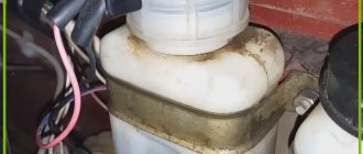
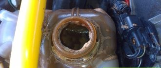
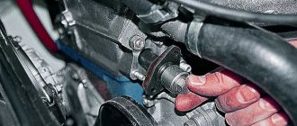
Where is the clutch reservoir located? Many people very often confuse the clutch reservoir with the brake reservoir, and therefore, so that you never get confused in these nuances, we will explain it right away. The clutch reservoir has always been and is currently located on classics closer to the fender, so that you understand in more detail, in this case, look just below the photo in which the hydraulic reservoir is clearly visible and indicated by an arrow.
When do you need to change the fluid in the clutch reservoir? As was said a little earlier, over time, any fluid loses its properties and thus can no longer normally perform the function for which it was created, therefore it is recommended to change the fluid in the hydraulic drive after five years of operation of the car, or if it gets into the system air that should not be in the system, and thus you have to bleed the clutch system of the car and thereby also have to replace the brake fluid in the clutch tank with a new one. (For information on how to bleed the system, see the very bottom of the article in the “Important!” section, there will be a link to bleeding the clutch on a VAZ)
What is needed to bleed the clutch of a VAZ 2107-2101
The procedure for bleeding the clutch on a VAZ 2101 in accordance with manuals for car repair and maintenance requires the presence of an assistant who will be directly in the car during repair work. However, this work can be done alone, although it will take more time. Also, in addition to having certain repair skills, the owner will need a certain set of tools:
- A simple rubber tube for bleeding air and waste fluid.
- New fluid to fill the clutch tank. As usual, ordinary brake fluid of the DOT-3 or DOT-4 standard is most often used as such a substance.
A set of keys for dismantling the master cylinder tank and other clutch parts in case of malfunctions.
In the case of self-repair and bleeding of the VAZ 2105 clutch, the owner will have to alternately carry out work both in the engine compartment and inside the car.
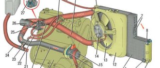
Clutch release drive device
The stamped clutch pedal 21 is mounted on a welded bracket 12, fixed to the body with bolts 11 and studs 8 with nuts 7. The clutch pedal swings on an axis 16, which is fixedly fixed in the bracket 12. The pedal is secured against rotation by a flat that fits into a shaped hole in one of the cheeks pedal bracket.
The axial movement of the axis is limited by the cotter pin 13 and the shoulder of the flat. Two polyamide bushings 17 rotating on an axis, having collars at one of the ends, are inserted into the pedal hub.
The bushings have high wear resistance and do not require lubrication during operation. A rubber pad 31 is put on the pedal platform. The pedal is held in its original (rearmost) position by the force of the tension spring 15. In this case, the non-adjustable pusher 14, pivotally connected to the pedal with a pin 19, rests against the limiting washer 5, fixed in the axial direction with a locking ring.
In the initial position of the pedal, the piston 12 of the clutch master cylinder under the action of the spring 8 abuts its end against the washer 14. Between the pusher 14 and the piston 4 there is a constant gap of a = 0.2 - 1.0 mm, which is ensured within the specified limits by the selected dimensions of these parts and the limiting washers 5.
We recommend: What is Tiptronic automatic transmission and how does it work
The specified gap provides the piston of the master cylinder with the opportunity to take its original position (with the clutch engaged), guaranteeing communication between cavity a of the cylinder and the filling tank 3 through compensation hole b.
In clutch and foot brake control drives, pedal axles, polyamide bushings, pushers, pedal linings and fasteners are interchangeable. The clutch master cylinder is designed to create pressure in the hydraulic clutch drive system. The cylinder has a cast iron body 9 with an internal diameter of 22 mm with a figured flange; Two pins 18 are screwed into the flange, with the help of which the cylinder and pedal bracket 12 are attached to the front panel of the body. During assembly, up to four (as needed) adjusting shims 6, made of sheet steel 0.5 mm thick each, are installed between the cylinder body flange and the front body shield. These spacers help establish the initial position of the clutch pedal, which should ensure its full travel L until it touches the rubber floor mat, equal to 150-155 mm.
Rice. Clutch release drive: 1 — bracket for fastening the connecting tube; 2 — connecting tube; 3 — clutch master cylinder assembly; 4 — piston of the clutch master cylinder; 5 — limit washer; 6 — adjusting gasket; 7 and 28 - nuts; 8 — master cylinder mounting pin; 9 — supply tank for the clutch master cylinder; 10 — nut holder; 11 — bolt of fastening of the clutch pedal bracket; 12 — clutch pedal bracket: 13 — cotter pin for the clutch pedal axis; 14 — piston pusher of the clutch master cylinder; 15 — clutch pedal release spring; 16 — axis of the clutch and brake pedals; 17 — bushing for the clutch and brake pedal axle; 18 and 33 - washers; 19 and 23 - fingers; 20 and 32 — cotter pins; 21 — clutch pedal; 22 — clutch release fork; 24 — pusher tip; 26 — release spring for clutch release fork; 26 - lock nut; 27 — fork pusher; 29 — clutch operating cylinder; 30 — pin for fastening the working cylinder; 31 — pedal pad; 34 — protective cap; 35 — retaining ring; 36 — piston of the working cylinder; 37 — sealing collar; 38 — spacer mushroom; 39 — spring; 40 — air release valve; 41 — valve protective cap; 42 — tube fastening bracket; 43 — gasket
At the top of the master cylinder body there is a tank 3 made of translucent plastic. The reservoir contains a certain supply of brake fluid necessary for the normal operation of the hydraulic clutch drive. The tank is closed with a plastic threaded cap 1, in which there is a hole to communicate the internal cavity of the tank with the atmosphere, and a reflective plate is attached to prevent the brake fluid from splashing out through the specified hole. The flange of the strainer 2 rests on the end of the supply tank, which simultaneously functions as a damper for the brake fluid in the tank.
The nutrient tank 3 is attached to the main cylinder body 9 with a threaded fitting 4, which has a slot at the end for a screwdriver. The sealing gasket 5 after tightening the fitting guarantees the tightness of the connection between the tank and the cylinder body. Through the hole in fitting 4, brake fluid from reservoir 3 flows by gravity into housing 9 of the master cylinder.
A rubber sealing collar 13 is placed on the piston 12 located inside the cylinder, which prevents liquid from leaking out of the cylinder. The piston is cast from zinc alloy. There are six through holes in the piston head, covered with a thin steel ring-valve 11 and an internal working rubber cuff 10. On the outer surface of the cuff there is one annular and six longitudinal grooves. Spring 8 presses the cuff against piston 12, and the piston against thrust washer 14. The other end of the spring rests against threaded fitting 7, which closes the internal cavity of the cylinder body.
A rubber protective cap 16 protects the internal cavity of the cylinder from dust. The cap is tightly placed on the groove in the cylinder body and the pusher rod 17.
The clutch slave cylinder 29 is secured with two studs 30 and nuts 28 on the left side of the clutch housing. The internal diameter of the working cylinder is 22 mm.
The main and working cylinders are connected to each other by a bent copper (6×1 mm) or two-layer steel tube 2 with copper-plated inner and outer surfaces (6×0.7 mm). The spiral located in the middle part of the tube compensates for the change in the distance between the ends of the tube, which is inevitable when the position of the power unit, suspended on rubber cushions, changes relative to the body. In addition to being secured at the ends, the tube has two intermediate attachment points: on the left mudguard of the body using bracket 1 and on the engine crankcase using bracket 42. Rubber gaskets 43 are laid between the fastener and the tube. The ends of the tube have a double conical flaring, the shape and dimensions of which shown in the figure. Before flaring the ends, connecting nuts are put on the tube, with which it is then connected to the main and working cylinders.
Rice. Clutch master cylinder: 1 — reservoir cap; 2 - mesh filter; 3 - tank; 4 — tank fitting; 5 — tank fitting gasket; 6 — master cylinder fitting gasket; 7 — main cylinder fitting; 8 - spring; 9 — main cylinder body; 10 — sealing collar of the main cylinder; 11 — piston valve; 12 - piston; 13 - piston seal; 14 - thrust washer; 15 — retaining ring; 16 — protective cap; 17 — piston pusher; 18 — master cylinder mounting pin
The housing 3 of the working cylinder is a casting made of gray cast iron, having on one side an open cylindrical cavity into which a cast aluminum piston 7 with a rubber sealing collar b, a spacer fungus 5 and a spring 4 are inserted. The spring constantly presses the spherical surface of the fungus against the sealing edge of the cuff and through it the edge to the cylinder mirror, which significantly improves the seal of the working cylinder, especially when there is no pressure in the system (the clutch is engaged).
Rice. Flaring the ends of the connecting tube (tube cross-sectional dimensions: steel - 6 X 0.7; copper 6 X 1.0)
Rice. Clutch slave cylinder: 1 — valve protective cap; 2 — air release valve; 3 - cylinder body; 4 - spring; 5 — spacer fungus; 6 - sealing collar; 7 - piston; 6 — protective cover; 7 - retaining ring
The conical valve 2 screwed into the cylinder body 3 serves to remove air from the hydraulic drive system. Rubber cap 1 is placed on the valve head and protects the internal channel of the valve from clogging.
We recommend: Car purchase
A pusher 27 is inserted into the spherical recess of the piston 36, which is adjustable in length. The pusher is adjusted by screwing it in or out of the fork tip 24. The position of the tip is fixed by the lock nut 26. The spring 25 of the clutch release fork 22 constantly presses the pusher to the spherical surface of the piston and, in the absence of pressure in the clutch hydraulic drive system, moves the piston to the extreme forward position. Since the piston 36 in the cylinder 29 can move in the direction corresponding to the clutch disengagement (to the right in the figure) only under the influence of the working fluid pressure, the formation of vacuum is eliminated, and therefore the penetration of air into the cylinder through leaks in the piston. Therefore, there is no need to maintain excess pressure in the connecting tube 2 and in front of the piston 36, which is usually provided by installing a double valve in the master cylinder, as is done in the hydraulic brake drive (see below). All parts of the clutch master cylinder, with the exception of housing 9 and fitting 7, are interchangeable with the corresponding parts of the brake master cylinder. Since the clutch master cylinder does not have a double valve, the body and fitting of this cylinder are different from the body and fitting of the brake master cylinder. To make it easier to distinguish between the clutch and brake master cylinders, their mounting flanges are rotated 60° relative to each other. A protective rubber cover 8 protects the internal cavity of the working cylinder from dirt.