ISO pinout or pinout is the identification of each electrical connection pin in a connector or diagram according to its corresponding numbering and functionality. The speaker system of any manufacturer is connected to the standard ISO connectors of the car. Proper pinout will help you get a good sound at the output and not burn out the connectors with voltage. You can understand the wires using standard diagrams. You can install any brand of car radio without having specialized knowledge in electrical engineering. When working with non-standard connectors, do not forget about safety. “Ring” the wires using a multimeter.
What is iso
ISO is an international organization that develops standards and regulations for various industries. The abbreviation sounds the same in all languages. A Russian manufacturer working in accordance with standards labels its products with the abbreviation “ISO” or “ISO”. All well-known developers of car radios equip their products with two types of standard plugs. Each looks like an eight-pin rectangular connector.
Possible problems and their solutions
During the operation of the presented car radio, various types of problems may occur. Their appearance is often caused by incorrect connection of underwater leads or a malfunction of third-party devices. In addition, malfunctions of the radio may be associated with power outages.
It is worth noting that in most cases, almost every malfunction has certain symptoms, based on which it is possible to determine its cause. With all this, it is worth noting that in order to eliminate a certain number of malfunctions, the owner will need at least minimal knowledge of electrical engineering and the presence of some measuring instruments.
Let's try to highlight the most common cases of problems.
Doesn't turn on
If, after installing the radio, it refuses to show signs of life, the following diagnostic measures should be carried out:
- make sure that the underwater leads are tightly connected;
- check the availability of power;
- make sure there is mass.
If all of the above measures do not lead to the desired result, there is a need to conduct a comprehensive diagnosis, which involves:
- checking the throttle and fuse L951;
- checking the voltage value of the Q952 stabilizer (operating voltage is 5V);
- checking the presence of a key on transistor Q609;
- checking the serviceability of MK/KK quartz oscillators.
If all of the above steps fail to identify the problem, it is highly likely that the problem lies in the IC601/IC901 microcontroller.
Doesn't turn off
Often, owners of Pioneer radios are faced with the fact that they simply cannot turn off the radio. Solving this problem will not be difficult if you find out some of the features of the devices of the presented type.
The shutdown algorithm looks like this:
- press key 2 and get to the Menu section;
- enable the Sustem tab;
- activate the PW SAVE function;
- turn off the radio by pressing the off button.
After saving the listed settings, to turn off the radio it will be enough to use key 1. When resetting the settings due to disconnecting the battery, etc., the specified algorithm should be repeated.
Pinout of a standard Euro connector
A Euro connector is a standard plug used in most countries around the world. When connecting equipment, you may encounter non-standard wires tangled in a bundle. This problem is solved by purchasing adapters and pinouting the radio chips.
Standards 1din and 2din
Speaker system connectors come in two types: non-standard ones from the manufacturer, mostly pin-type, and standardized European ones, which are located at the back. Installation of equipment with a special audio connector from the manufacturer will require the use of a special proprietary connector. If the plug is ISO, then you can connect to it directly. There are two types of Euro connectors: 1din and 2din, the difference is in the height of the car radios. The two-block one is twice as tall; it is not connected to all cars, because there is no space on the panel for the required dimensions.
Radios with European 1din are the most common.
When installing car radios, wires with a small diameter of 1.5-2 mm are used, for power lines - with a large cross-section. Failure to follow these simple rules will distort the sound and damage the equipment.
| № 1 | — |
| № 2 | — |
| № 3 | — |
| № 4 | Constant power |
| № 5 | Antenna power |
| № 6 | Backlight |
| № 7 | Ignition |
| № 8 | Weight |
Manufacturers in Japan, the USA and some Chinese use the 2din standard.
Upper power connector A
The plug is used to supply electricity to the receiver, antenna and amplifier, as well as when it is necessary to control the backlight or turn off the sound signal. Standard color markings are used. Outputs 1-3 and 6 are not used in low- and mid-price segment speakers; they are intended for additional options for high-end products.
Connection types
- The first is the connection in the socket of wires of two colors, yellow and red, turning the receiver on/off does not depend on the ignition. The method is inconvenient because it predisposes the battery to discharge if the acoustics are not turned off;
- The second wire is connected through the ignition switch, the yellow wire is connected to the on-board computer.
Functional purpose of the receiver outputs
| ANT | The connector is used if the car has a retractable antenna |
| Remote | Multiple speakers can be connected |
| Illumination | Allows you to change the intensity of the device's glow |
| Mute | Adjusting the sound |
| A4 | Turn on/off |
Pinout of radio ISO connector
| A 4 | Color yellow | Battery + Power |
| A 5 | Color blue | Antenna. |
| A 6 | Color orange | Backlight |
| A 7 | Color red | Ignition, 12V. When disconnected, reset settings to factory settings. |
| A 8 | Color black | Acoustics |
Bottom speaker connector B
Used to connect amplifiers (2 cables each). The sound of the equipment depends on whether all connectors are connected correctly. The main thing is not to confuse them, otherwise the acoustics will be of poor quality.
Rules for connecting speakers by color marking of wires
| Color white | Left front |
| Color grey | Right front |
| Color green | Left rear |
| Color violet | Right rear |
Troubleshooting a Wrong Connection
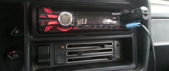
If you bought a Sony car radio and need to connect it instead of the standard one, or you have become the owner of a car where the control unit from this manufacturer is not connected correctly, then these instructions will help you fix everything.
Car radio connector pinout
So, it often happens that a Sony car radio is connected “without a key”. In other words, the connection was made directly from the battery, without an ACC wire. In addition, the confusion of wires in the circuit can lead to a situation where one of the front speakers plays and one of the rear speakers plays. All this is corrected like this. Removing the radio:
- The mass is removed from the battery so that while digging in the wiring it is not accidentally shorted;
- The insert on the center panel box is pulled out and pulled up from the front;
- The screws located above the climate control control console are turned out (at least this is the case on many foreign car sedans);
- The ashtray is removed;
- The front panel of the Sony car radio is removed from the mounts and then moved to the side;
- 4 screws fixing the central blocks are removed;
- The car radio is removed.
- There are a bunch of wires behind the radio that need to be studied according to the connection diagram for the control unit with ACC (see above);
Wiring
Sony car radio connection diagram
- In addition, you need to study which wire goes where;
- If you believe this wiring diagram, then just swap the green and white wires to solve the problem with the speakers;
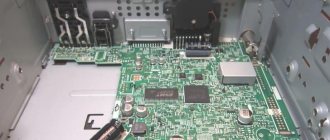
- In the photo below you can see that the small chip on the left is responsible for the rear acoustics, and the large chip with 8 wires (on the right) is for power and front;
Sony car radio wires
- You should also pay attention to the fact that the radio is connected with 2 positive wires: one of the wires is yellow and the other is red. They are connected together and connected to DC current, bypassing the ignition switch, as here;
Yellow and red wires together
Note. As a rule, the black wire is responsible for ground, brown or yellow for constant power, pink with a blue stripe for power from the lock. The remaining wires go to the front speakers.
- The red wire breaks, and the insulation from the wire with the blue stripe is unscrewed. The two wires are twisted together and insulated;
- All wires are wound back. Don't forget to swap the white and green wires going to the speakers;
- The GU is connected and everything is checked like this: if the key in the lock is in position 1, the radio is turned off, if the key in the lock is in the ACC position, the radio is on.
Note. The wires must be cut using heat shrinks. During this operation, you can at the same time adjust the control panel to the woofer at the rear. It will be enough to pull out the cup holder and run the wire to the subwoofer under it. That's it.
Now, dear reader, you know what all the intricacies of connecting a radio mean, at least in theory. As for practice, there is no need to rush to start it until you have watched a video review on the topic, studied the diagrams and photo materials in detail. When working with your own hands, you must not forget that the wires must be well insulated. Independent troubleshooting and the ability to connect a car radio is a valuable thing. Now you can save on expenses that are inevitable when calling a specialist, the price of whose services sometimes causes confusion among most Russians.
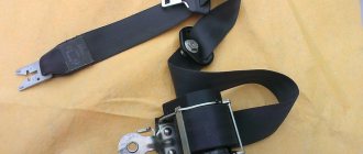
Dual ISO connector
The standard audio systems of some cars are connected with a double plug. The pinout of connectors for them is standard. The contact halves are connected to each other by a durable plastic jumper and secured with a special clamp. For correct installation, a guide groove is used, which prevents the plug from being installed in the wrong position.
The black one connects a current source to the radio, the brown one for acoustics.
Installation of 2 din radio
The situation is somewhat different in the case when a 2 din standard radio tape recorder claims to replace the old radio. The installation procedure for such a radio will be painless if the old analogue meets the same standard. Otherwise, a number of problems may arise.
Firstly, if you replace the standard 1 din standard configuration with 2 din, you will have to replace a number of elements: the center console, frame, etc.
In addition, during these events you will definitely encounter various undesirable phenomena that will not have the best effect on the aesthetic component of the interior of your car.
Based on all of the above, it is quite reasonable to draw one single conclusion: select an audio system that meets the standards provided by the manufacturer of your car.
Video instructions for connection and setup
To learn more about the intricacies of connecting a Pioneer car radio, follow the link below. The presented video review highlights the main stages, features and recommendations on the topic under consideration.
Adapters for ISO connectors
Cutting off a non-standard standard plug and connecting the wires directly is not recommended, because over time the connection will become loose, may oxidize, you will have to solder not only the wiring, additional repairs will be required, replacing blown fuses. Sometimes there are acoustics with three outputs, but they have standardized markings and electrical circuits that allow you to connect standard cables to the device using pinouts. You can buy any type of adapter for ISO connectors from one model to another.
The car may not be equipped with connectors, then you need to connect the radio connector to the cable directly. This is done by twisting, soldering, or using a terminal block that does not require subsequent insulation. When twisting and soldering, heat shrink tubing is used for safe use of the equipment.
How to connect a radio
If the instructions or reference label are lost, then before connecting the car radio correctly, you need to check the purpose of the wires using a tester, a suitable current source and a low-power 12-volt light bulb. First, the wires intended for connecting power are recognized.
This procedure also needs to be done if they have different colors than the standard or are not equipped with fuses. For safe detection, you can use a 9-volt battery as a power source. Its negative pole is connected to the car radio body. The positive terminal of the battery is connected in turn to each cable of the car radio. On an old radio, you also need to press the switch or turn the volume control.
At the moment of connection to the cable intended for supplying power, a weak spark will jump between the contacts. If the battery is fully charged, the backlight will light up faintly. On modern radios, the correct connection of the circuit can be confirmed by pressing the Power button. After this, the power will turn on.
Then the wires that give current relative to the minus (radio casing) are determined. To do this, connect a 12 V current source to the previously recognized contacts to supply power. A 10 A fuse must be included in the positive gap in order to increase safety.
A light bulb or tester rated for 15 V or more is connected to the cassette recorder body and alternately to the remaining cords after turning on the device. If the arrow deviates and the light comes on, then the wire is intended to power the antenna or remotely control the amplifier. All cables identified by color must be clearly marked.
Pinouts for various brands of cars and radios
Before getting started, read the instructions for the receiver, and also pay attention to the markings and features of the product itself. The pinout of radios is influenced by standard connectors in different cars.
Pinout diagram for ISO connectors for pioneer radios
Connecting the acoustics of this well-known brand, which is popular among motorists, has some features. Be sure to read the installation manual before starting work. Installation is simple, the main thing is to understand the purpose of each color. In addition to the instructions, the kit includes two “chips” with 4 pairs of contacts: for power and acoustics.
The pinout of the plug has 10-20 outputs, the functionality of each connector varies depending on the model. The KEH series is characterized by the following circuit: No. 1 - antenna, No. 2 - ignition, No. 3-6 and 8-11 - amplifiers. To avoid confusion, please read the instructions carefully.
In order not to burn out the acoustics, before connecting the speakers you need to connect the radio, check that it lights up and switches.
toyota
The pinout of acoustics of this brand is carried out according to standard diagrams. It is optimal to choose a power supply system from a battery, in this case there is no risk of its discharge.
ISO connector:
| № 1 | A+ |
| № 2 | GND |
| № 3 | BAT+ |
| № 4 | Backlight |
| № 5 | Antenna |
| № 6 | Speakers (RR+, RR-, RF+, RF-, LF+, LF-, LR+, LR-) |
sony
When connecting the radio, standard circuits are used.
| № 1 | ANT |
| № 3 | L.R. Line output |
| № 4 | GND. Line output |
| № 5 | R.R. Line output |
| № 6 | CD–LCH |
| № 7 | CD - GND |
| № 8 | CD–RCH |
| № 9 | CD - Reset |
| № 10 | CD – CD clock out |
| № 11 | CD – DSPL select |
| № 12 | CD – data out |
| № 13 | CD – clock in |
| № 14 | CD – data in |
| № 16 | A+ |
| № 17 | GND |
| № 18 | ANT GND |
| № 22-27 | Speakers (LF-, LR+, RF-, RR+, LF+, LR-, RF+, RR-) |
| № 28 | Mute |
| № 29-30 | Speakers (LF-, LR+, RF-, RR+, LF+, LR-, RF+, RR-) |
| № 31 | ANT CONT |
| № 32 | CD ACC Constant |
| № 33 | AMP Constant |
| № 34 | BUP |
nissan
Universal connector:
| № 1-6 | Speakers (LR+, RR+, LR-, RR-, LF+, RF+) |
| № 7 | A+ |
| № 8 | Backlight |
| № 9 | BAT+ |
| № 10 | Speakers LF- |
| № 11 | RF speaker |
| № 12 | Antenna |
| № 13 | GND |
honda
All models of car radios are equipped with a universal European plug for connection to the socket.
| № 1 | Speaker RR+ |
| № 2 | Speaker LR+ |
| № 3 | Backlight |
| № 4 | BAT+ |
| № 5 | A+ |
| № 6 | Antenna |
| № 7-10 | Speakers LF+, RF+, RR-, LR- |
| № 13 | GND |
| № 14-15 | Speakers LF-, RF- |
bmw
Standard European pinout.
| № 1 | A+ |
| № 2 | BAT+ |
| № 3 | GND |
| № 4 | — |
| № 5-12 | Speakers RR+, RR-, LF+, LF-, RF+, RF-, LR+, LR- |
alpine
Alpine TDE-7823W: 1 – BAT+,
| № 2-5 | Speakers LR-, LR+, RR-, RR+ |
| № 7 | Amplifier |
| № 8 | Antenna |
| № 9 | GND |
| № 10-13 | Speakers LF-, LF+, RF-, RF+ |
| № 5-12 | A+ |
mitsubishi
All models use standard European speaker pinout.
| № 1-2 | Speakers RR+, LR+ |
| № 3 | Antenna control |
| № 4 | Backlight control |
| № 5-8 | Speakers LF+, RF+, RR-, LR- |
| № 10 | A+ |
| № 11 | BAT+ |
| № 12 | Backlight control |
| № 13-14 | Speakers LF-, RF- |
| GND |
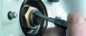
Removing an old car radio
So, the treasured radio is waiting in the wings. It's time to get rid of your old audio system. At first glance, it may seem that this procedure is not complicated. By and large, this is true. However, there are a number of nuances that it is advisable to take into account during dismantling.
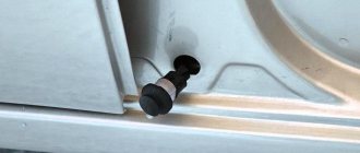
Note for you: How to remove a radio without pullers and keys
At the initial stage, in order to avoid damage to the panel elements, it is necessary to find out how the radio is secured in the niche.
Depending on the type of car audio system, there are several mounting methods:
- using flexible metal tongues;
- using plastic clips;
- using a screw connection.
As a rule, if we are talking about a standard radio, there is a last method of fixation. Often, the manufacturer, pursuing an aesthetic goal, masks the heads of screws or screws with plastic caps. Dismantling such a radio should not cause serious difficulties. To do this, it will be enough to unscrew the screws and gently pull it out.
The situation is somewhat different when the radio is located inside a metal casing. In this case, special keys will be required to remove the radio. Hardly anyone remembers their existence when this kind of need arises. However, all radios of the presented type are equipped with them.
The principle of fixing such a radio is not very complicated. Flexible metal tongues with a protruding part are attached to its side walls. On the casing, in a strictly verified place, there are special recesses. The aforementioned tabs go into them, rigidly fixing the radio in the casing.
If you don’t have a key, you can use two thin metal plates to remove it. To do this, you need to insert each of them between the frame and the radio, thereby squeezing out the metal tabs.
After this, you should pull the radio towards you, turning it slightly in different planes. It should be noted that this kind of tricks of manufacturers is nothing more than measures of protection against lovers of easy money.
In addition, radios can be installed in the panel using plastic clips. With this method of fastening, it is important to prevent distortion of the plastic frame. To avoid damage, the clips should be released gradually and evenly, avoiding distortions.
Useful to read: What is a diesel intercooler: principle of operation and causes of failure
With any method of fixing the radio, its dismantling must be done carefully so as not to damage the integrity of the connecting wires and contacts.
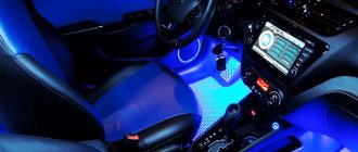
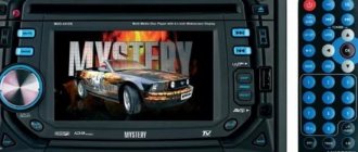
Review of car radio Timeless TID 9301
Car radio with GPS navigator
Let's consider one of these car radios. It differs in the following technical characteristics:
- The screen of the device is motorized 7 inches. Has a resolution: 1440x234 pixels;
- GPS navigator is built into this head unit;
- The car radio supports ipod (see How to connect an ipod to the car radio with your own hands);
- It has an AUX jack on the front panel;
- A radio tuner operating in the FM/AM bands is built into the car radio;
- It is possible to connect the controls to the buttons on the steering wheel;
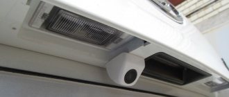
- There is a separate camera output;
- The device comes with a block with wires, instructions, a remote control, wires for USB, a mounting frame and special tools for removing the radio.
Connection
Let's now find out how to connect this device. Using the same example, you can connect other car radios similar in parameters to this one. Let’s begin:
As in the case described above, we ground the gray wire to disable the protection for watching DVD programs;
The window lifter does not work - do it yourself repair of window lifter buttons on a Renault car
Car radio with GPS navigator and its connection
We use the AMP-CON wire, designed to control external sources.
In addition to the wires described above, the car radio has built-in connectors for connecting AV wires. In particular, there is an input for Camera IN, where the wire from the rear camera is inserted, there are outputs for the rear and front channels, audio and video, and so on. In this case, colored wires are used.
The front console of the car radio is a panel containing the following components:
- The display is single-line, thanks to which short information is displayed (if the LCD screen is removed). This very display has 7 types of backlight;
- Here, on the front console, you can find a Bluetooth receiver (see Bluetooth for car radio: do it yourself);
- To open the LCD panel there is an OPEN button;
- There is also a volume control, microphone, AUX jack and much more;
- Placed on the front console and SD card slot;
- There is also a mode switching regulator on the front panel, and a mini USB on the right side.
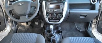
It is interesting that this same model of car radio can be easily installed on a VAZ 2105. There are no problems with installation, although some parts of the dashboard will still have to be cut out. Knowing how to configure GPS car radios with your own hands is very useful. You can save a lot of money on the services of specialists, who sometimes charge such prices that it’s scary to even think about. The main thing is to do everything according to the instructions, do not ignore video reviews and photo materials.
Decoding the wires of radio tape recorders for cars
Decoding the wires of radio tape recorders - designations, decoding of contacts and wires of car radios.
Acoustic group
R = Right speaker.L = Left speaker.FR+, FR- or RF+, RF- = Front right speaker (plus or minus, respectively).FL+, FL- or LF+, LF- = Front left speaker (plus or minus, respectively ).RR+, RR- = Rear speaker - right (plus or minus, respectively).LR+, LR- or RL+, RL- = Rear speaker - left (plus or minus, respectively).GND SP = Speaker common wire.
Radio power connector
- B+ or VAT or KZO or Vir+ or B/Up or B-UP or MEM + 12 = Battery power (plus)
- GND or GROUND or K31 or just a minus = Common wire (Ground), battery minus.
- A+ or ACC or KL 15 or SK or S-kont or SAFE or SWA = +12 from the ignition switch.
- N/C or n/c or N/A = No contact. (Physically the output is there but not connected anywhere).
- ILL or LAMP or sun symbol or 15b or Lume or iLLUM or K1.58b = Panel illumination. +12 volts are supplied to the contact when the side lights are turned on. Some radios have two wires, -iLL+ and iLL-. The negative wire is galvanically isolated from ground.
- Ant or ANT+ or AutoAnt or P.ANT = After turning on the radio, +12 volts are supplied from this contact to control the retractable antenna, if one is present, of course.
- MUTE or Mut or mu or the image of a crossed out speaker or TEL or TEL MUTE = Input to turn off or mute the sound when receiving a phone call or other actions (for example, reversing)
Other possible contacts in radios
Power Control = this is the control for turning on the amplifierP.CONT/ANT.CONT = this is the control of the antenna, power is supplied after turning on the radioILL + and ILL - = these are the wires for adjusting the brightness of the radio backlightAmp = Control contact for turning on the power of the external amplifierDATA IN = Data InputDATA OUT = Data OutputLine Out = Linear outputREM or REMOTE CONTROL = Control voltage (Amplifier)ACP+, ACP— = Bus lines (Ford)CAN-L = Bus line CANCAN-H = Bus line CANK-BUS = Bidirectional serial bus (K-line)SHIELD = Connection braided shielded wire.AUDIO COM or R COM, L COM = Common wire (ground) of the input or output of preamplifiers CD-IN L+, CD-IN L-, CD-IN R+, CD-IN R— = Balanced linear audio signal inputs with changerSW+B = Switching power supply +V battery.SEC IN = Second inputDIMMER = Changing display brightnessALARM = Connecting alarm contacts for the radio to perform car security functions (PIONEER radios)SDA, SCL, MRQ = Exchange buses with the vehicle display.LINE OUT, LINE IN = Line output and input, respectively. D2B+, D2B— = Optical audio link
Marking and color coding of wires
Let's look at the color code for car radio wires:
- Black (indicated by GROUND or GND) is the negative of the battery;
- Red (ACC or A+ marking) is the plus of the ignition switch;
- Yellow (indicated by BAT or B+) is the positive from the battery;
- White with a stripe (marked FL-) is the minus of the front left speaker;
- White without a stripe (indicated by FL+) is a plus of the front left speaker;
- Gray with a stripe (marked FR-) is the minus of the right front speaker;
- Gray without a stripe (indicated by FR+) is a plus for the right front speaker;
- Green with a stripe (marked RL-) is the minus of the left rear speaker;
- Green without a stripe (designation RL+) is a plus for the left rear speaker;
- Purple with a stripe (marked RR-) is the minus of the right rear speaker;
- Purple without a stripe (designation RR+) is a plus for the right rear speaker.
Next, you can see how the car radio connector is pinned out.
Marking and color coding of wires
Let's look at the color code for car radio wires:
- Black (indicated by GROUND or GND) is the negative of the battery;
- Red (ACC or A+ marking) is the plus of the ignition switch;
- Yellow (indicated by BAT or B+) is the positive from the battery;
- White with a stripe (marked FL-) is the minus of the front left speaker;
- White without a stripe (indicated by FL+) is a plus of the front left speaker;
- Gray with a stripe (marked FR-) is the minus of the right front speaker;
- Gray without a stripe (indicated by FR+) is a plus for the right front speaker;
- Green with a stripe (marked RL-) is the minus of the left rear speaker;
- Green without a stripe (designation RL+) is a plus for the left rear speaker;
- Purple with a stripe (marked RR-) is the minus of the right rear speaker;
- Purple without a stripe (designation RR+) is a plus for the right rear speaker.
The radio arrived from China today, but I can’t figure out how to connect it.
What are the wires used for and where do they go?
Wires for car radios are used to connect to a power source, speakers and amplifier, remove control signals and implement service functions. Thanks to clear identification by color, the likelihood of making a mistake when connecting is reduced, since it is clear which wires go where and what they are needed for.
Orange
The orange wire (ILL) is most often used to control the backlight of the car radio display. It connects to the parking light switch. In this case, several backlight control scenarios are possible. For example, you can make its brightness automatically decrease when the side lights are turned on.
Yellow and red
According to the generally accepted standard, the yellow and red wires are used to connect the positive pole of the power supply to the car radio. Through the first of them, constant power is provided to the device’s microcircuits along with the audio power amplifier and display backlight. When voltage is applied to the yellow cable, all functions of the car radio begin to work. Often, its break is connected to a fuse in a housing that matches the type. The higher the output power of the car radio, the higher the rating of the fuse link.
The red wire, constantly connected directly to the battery, provides continuous power to the volatile memory chip, which stores radio stations recorded by the owner, car radio parameters and the place where listening to music from the media was stopped. The yellow wire is often connected not directly to the on-board network, but through the ignition switch. Thanks to this approach to power supply, the current consumed by the receiver is reduced several times.
The radio does not read the flash drive (note to motorists)
Blue and pink
The blue wire is used by some manufacturers to control a motorized antenna. It is supplied with power when the radio mode is turned on. When the radio is turned off, the antenna is automatically retracted, since it contains an additional relay, which is powered directly from the battery. Another purpose of blue is to enable additional functions. For example, the Reverse wire on the radio is used to activate the parking sensors or rear view camera mode.
Pink is used to implement various service functions. One of them is blocking multimedia functions on a 2-din radio with a video player. The control signal is most often supplied from the warning lamp switch under the parking brake lever. As soon as the pink cable is connected to ground, it becomes possible to start the video player or turn on the TV tuner. Otherwise an error message will appear on the display.
Blue - white
The blue-white cable (blue wire with a white stripe) is designed to control the power of the active antenna. It is often marked with a tag marked “Remote”. This cable also supplies a control signal to the car amplifier. The connection can be made either directly to the device or through a special relay.