Scheme for connecting the alarm system to the Central Lock on a Priora
This diagram is the simplest diagram for connecting an alarm system to a standard Priora Central Lock.
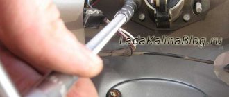
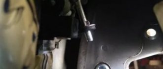
To implement this scheme, we lay two wires in the driver's door and connect them to the gap in the brown wire between the electric drive and the driver's door module.
When connecting the central locking according to this scheme, all doors will close, and only the driver’s door will open, the rest are opened by a button in the driver’s door.
If the standard alarm is activated, you can reprogram it so that all doors are opened simultaneously using the alarm key fob. To do this, with the ignition on, press both buttons on the key simultaneously until the signal sounds. One signal enables this function, two signals disable it.
The alarm connection points for Priora are located here.
Many car owners prefer to install security equipment on their own. For self-installation, you need to determine the alarm connection points on the Priora, and then connect the cables with subsequent insulation of the joints.
Repair of vacuum central locking
Common malfunctions of vacuum central locking:
1.Opening and closing of door locks continues until the pump stops working.
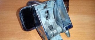
The cause of the malfunction is condensation formed during temperature changes. The driver's door actuator switch contact malfunctions. The switch is dismantled and the condensate is removed. It may need to be replaced.
2. Uneven operation of car door locks.
On some doors, the locks close late or continue to remain open after receiving a command from the control panel. The compressor continues to operate until it is switched off by the protection system.
The vacuum line tubes are checked for leaks. The door line where the fault was found is inspected. Damage can be detected by hearing by the characteristic hiss of escaping air. Damaged tubes require replacement.
The pump control board does not receive a signal to close the door locks. He continues to circulate air. Damage to the electrical wire occurs in the door corrugation.
The signals reach the pump board, but it continues to work ignoring them. To repair the fault, the compressor unit is disassembled. The oxidized terminals of the alarm pneumatic sensor are being cleaned. If these steps do not help, then the pump control board has failed.
Two schemes (simple and complex)
First of all, before connecting the alarm, you need to study the instructions included with it. The main unit always has relays installed: one of them closes when the locks are locked, the second acts on opening. The connector to which the relay contacts are connected usually has 6 pins. There is nothing complicated here.
In the first case, we will use only this connector. The second circuit uses another contact, called “signal output for 2-step lock opening”. Find it on the main unit.
We connect the alarm in a simple way
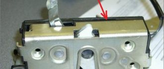
A push-button module is installed in the driver's door of the Lada Priora. The door trim must be removed and the connector for this module must be found:
We will need a brown cord from the connector. It is a signal, and the alarm relay is connected to its break:
Procedure when the window regulator does not work
The design of the Priora's window regulators differs from the usual ones, which use a relay and a window regulator fuse. AvtoVAZ made the glass control using an electrical package control controller (TSBKE), which is located near the ECU.
1. Check the TsBKE fuse in the mounting block (F31, 30A).
2. Remove the door trim and check the voltage at the power window motor terminals using a multimeter or a 12V test lamp.
If there is no voltage, then check the serviceability:
- window control unit (buttons in doors)
- wiring (connector connection)
- electrical package control unit, which is located above the ECU unit (more on this below)
If current flows to the electric motor, but the glass does not move, then we check:
- malfunction of the window lift motor (for example, the drive motor brushes are stuck/sticking, the plastic gear in the gearbox is worn out)
- The window lift cable is frayed
- glass is jammed (distorted)
The most common problems with power windows are:
- Faulty double-glazed window control unit (GCU)
- Window lift motor malfunction
- Skewed, broken power window cable
- Poor contact
Connection points
Power is supplied to the security system from the ignition switch; the negative terminal is attached to a metal element connected to the car body. To operate the remote engine start unit, you need to use the cable coming from the limit switch under the parking brake lever. Information about the operation of the motor is transmitted to the head unit via a separate cord connected to the speed sensor.
Lada Priora alarm connection points include cables going to switches mounted in the doors, under the lids of the luggage compartment and the power unit compartment. Additionally, the wires of the original siren (or an alternative unit) are connected. If the alarm system supports switching of the CAN-LIN digital bus, then it is also necessary to connect the points (in accordance with the factory documentation).
- Repair of door locks for VAZ 2108, VAZ 2109, VAZ 21099 cars
Connecting the central lock
To connect the alarm system to the Priora central locking system, a cord is used that goes to the control controller. The cable is covered with brown insulation. With a direct switching scheme, all door locks are locked simultaneously, but when the security is disarmed, only the driver's door will open. If the car owner wants to open other doors based on a signal from the remote control, then a 2-stage shutdown scheme is implemented.
The car owner connects an additional relay to the circuit, which operates in parallel with the contact units for blocking the power windows of the doors. If you do not install a window drive relay, then when a signal is sent to the central locking system, the motors will briefly operate (to lower or raise the windows). This occurs due to the design features of the electrical wiring harnesses and electrical components installed in the doors of Priora vehicles. Some cars use 1 relay (in the absence of rear electrical mechanisms).
Determining malfunctions of the central locking
Failure of the central locking system cannot occur spontaneously. There are harbingers indicating that the system is not working correctly or malfunctioning. They cannot be ignored. It is necessary to determine the cause of the malfunction as quickly as possible.
Reasons for failure of the car's central locking system:
1. Complete refusal.
Does not respond to pressing buttons on the key fob sending commands to the central control unit. Often the cause of the malfunction is trivial. A discharged key fob battery prevents sending a command to open or close locking devices.
2. Partial refusal.
It is characterized by alternating periods of normal operation in normal mode and a complete refusal to respond to remote control commands.
3. Malfunction of locks.
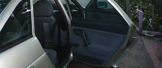
The malfunction manifests itself as chaotic operation of the locks. They can randomly close, open or be completely blocked without responding to incoming commands. The malfunction is dangerous because the doors can be completely blocked without the possibility of mechanical opening. You have to remove the door trim and open it manually.
Before you begin repairing the central locking system, you must determine the cause of the malfunction.
The procedure for localizing failures and disturbances in the system:
1. Alarm testing.
If the central locking is combined with an alarm system, it is necessary to inspect it first. The door locking devices do not respond to signals from the control panel; they must be checked mechanically using the ignition key.
If the central locking operates in manual mode, you need to check the electrical and control circuits of the alarm. One of the common options is that the battery in the key fob may have run out.
2. The central locking does not work completely or partially.
When testing the central locking system, it refuses to work or operates irregularly in manual mechanical mode using the ignition key. It is necessary to clarify the nature of the manifestation of the malfunction.
If there is a complete system failure on the vacuum central locking system, the compressor operation cannot be heard. The electric central locking responds with weak, barely audible clicks of the operating relay. The locking device buttons remain stationary.
It is necessary to locate the central locking circuit fuse. If it is burnt out, replacing it will solve the problem of mechanism failure. Depending on the car model, there may be more than one fuse.
3. The system fuses are intact and undamaged.
If it is determined that the fuses are safe and sound, you must continue to persistently examine the system to determine the cause of the malfunction.
The cause of malfunctions in the operation of locking devices may be the lack of voltage supply to the input elements of the driver's door actuators. The malfunction occurs after wire breaks or terminal oxidation and breaks contact.
The driver's door drive cannot transmit the signal received by it from the control panel to the other doors. Similar symptoms appear when the driver's door actuator limit switch is faulty. The control signal is not detected.
Repair work on the central system must begin with checking the power supply and control signal. It is necessary to visually check the system wires for damage. The limit switch must be checked. It is installed inside the drive.
4. Arbitrary opening or closing of door locks.
Often, after pressing the key fob button, the door locks close and after a few seconds randomly open. The opposite sign of a malfunction also appears when the locks close without giving a signal.
The cause of the malfunction is a violation of the fixation of the rod fasteners. Located between the drive and the driver's door lock mechanism. There is a violation of the process of unlocking and locking doors.
Notes on implementation of schemes
Let us immediately note: if there are no window lifters, the second diagram will not contain parts K2/K3. Then you only need to cut one wire. Sometimes only the rear windows are missing. This means that relay K3 is excluded. And the diodes connected in parallel with the winding can be absolutely anything.
Now we list the requirements for an element called “relay”:
- Operation voltage - 12 Volts;
- Switching current - 10 A or higher;
- The current consumed by all relay windings should not exceed the value specified in the instructions for the signaling. Usually it is 200-300 mA.
It is the last requirement that is often violated.
In order for “scheme 2” to work, it is necessary not only to assemble it, but also to program the main unit: you need to enable the “2-step unlocking” option. And be that as it may, control impulses cannot be made too long. Use values of 0.7-1.1 seconds.
Electronics
In addition to the reasons described above, the problem may lie in small electronics. The check should begin with the key fob. First of all, the battery and the condition of the buttons are checked. Perhaps they stick and do not work at the right time. If the board itself is faulty, the key fob simply will not respond to external stimuli. The LED on its body will not light up. It's good if you have a spare key fob. Otherwise, you will have to change the alarm, or find exactly the same key fob.
Next, the alarm control unit is checked. The verification method is usually indicated in the instructions. Lastly, they check the microboard located on the central locking drive motor. At the same time, they look at the condition of the drive itself. All failed parts are replaced. The most difficult thing is with the control unit. It is practically beyond repair. Therefore, it is much easier to install a new alarm. Sometimes the key fob loses synchronization with the unit, then it will have to be reprogrammed.
Connecting limit switches
The signal cables from the limit switches are connected to the electrical control unit, which is located inside the car. From the front doors there are cables with blue-black and brown insulation; wires with gray-red protection are laid to the rear elements. An additional yellow-red cord is routed to the luggage compartment lid lock. The engine compartment hood switch is covered with white and black insulator. Before starting the connection, it is recommended to check the purpose of the cables according to the electrical diagram of the machine.
1.1.2 Doors, central locking
Doors, central locking
| GENERAL INFORMATION |
When you unlock or lock the front doors or the luggage compartment, the central locking system simultaneously unlocks or locks all doors, the fuel filler flap and, depending on the position of the luggage compartment lid lock, this lock as well.
The central locking system is equipped with self-insurance: after the car is locked from the outside, the internal door lock buttons are immediately activated. Thus, the likelihood of unauthorized persons entering the cabin is reduced. The central locking system can also be controlled from the outside using either the key or radio remote control.
Control points for locking and unlocking the vehicle
Outside: front doors, trunk lid (station wagon rear door).
Inside: central locking control button in the driver's door handle.
Unlocking
To unlock your vehicle, turn the key in one of the front doors or in the trunk lock to the unlock position.
All door lock buttons rise.
The self-belay and security alarm system are immediately turned off, which is accompanied by a short flashing of the direction indicators.
When the vehicle is unlocked, the interior lamps whose switches are in the door contact control position come on for approximately 20 seconds.
If the central door locking system fails, you can, in general, operate all the locks in the usual way. However, self-insurance cannot be activated if the normal operation of the central locking is disrupted.
Holding the key in the unlock position will open all windows on vehicles with electric windows.
If the central locking system fails, the rear doors cannot be unlocked from the outside.
If there is a violation in the normal operation of the central locking, this is indicated by the flashing of the backlight of the power window control switches of both front and rear doors. You should contact a Volkswagen service company.
Locking
To lock your vehicle, turn the key in one of the front doors or in the trunk lock once to the lock position. All doors and luggage compartment will be locked. The lanyard and security alarm system will immediately be activated, accompanied by a brief flashing of the direction indicators.
When the vehicle is locked, the interior lamps whose switches are in the door contact control position are switched off.
The functional readiness of the lanyard is indicated by the blinking of the warning lamp located near the driver's door lock button.
Warning
No one should be in a car that is locked from the outside; first of all, young children should not be left there, since the doors cannot be opened from the inside. This is especially important in the case of cars with electric windows, because in this case the windows cannot be opened.
If you turn the key in the corresponding lock twice in a row within one second, all doors and the trunk lid (the rear door of the station wagon) will be locked. The lanyard and security alarm system will not be activated.
When the lanyard is turned off, the car can be unlocked from the inside. To do this, you should pull the inside lock handle of the corresponding door until the lock button is raised. If you pull the lock handle again, the door will open.
On vehicles equipped with electric windows or a power sunroof, the door windows or sunroof left open can be closed centrally. To do this, hold the key in the locking position until all door windows and the sunroof are completely closed.
The doors can also be locked by pressing the door lock buttons. However, self-locking is not activated.
When the driver's door is open or not completely closed (the door is not fully locked), the car locks do not lock. If the car is locked using the front left door or trunk lid (rear door) lock, this door or trunk lid (rear door), like the driver's door, must be completely closed.
How to unlock only one of the front door locks or the trunk lid (rear door)
Central locking also provides the ability to unlock either of the two front doors, as well as the luggage compartment, while all other locks remain locked. For more detailed information and practical implementation of this possibility, contact a Volkswagen service company.
Unlocking when the unlocking mode of one of the locks is on
Turn the key in the appropriate lock once: the driver's or front passenger's door or trunk lid (rear door) is unlocked. The self-belay and security alarm system are immediately turned off, which is accompanied by a short blinking of the direction indicators.
Turn the key in the corresponding lock twice in a row: all doors and the trunk lid (rear door) are unlocked. The self-belay and security alarm system are immediately turned off, which is accompanied by a short blinking of the direction indicators.
Central locking key
The central locking key allows you to lock or unlock all the car's locks from the inside. The key is located in the left door handrail.
Blocking
By pressing the right side of the A key. all doors and trunk lid (rear door) are locked. Opening the doors and trunk lid (rear door) from the outside or unwanted intrusion into the vehicle (for example, when stopping at a traffic light) is no longer possible.
When the driver's door is open, it does not lock. This eliminates the situation where the driver finds himself outside a car locked from the inside.
The self-belay and security alarm system do not turn on when the key is pressed.
Unlock
By pressing the left side of the B button, all doors and, depending on the position of the luggage compartment lock, the luggage compartment are unlocked.
When the car is locked using a key, it is possible to unlock the doors individually. To do this, pull the inner lock handle of the corresponding door until the lock button is raised. Pulling the handle a second time will open the door.
The key switch also functions when the ignition is off.
Warning
If the central locking button in the handrail in the driver's door is pressed, the locks of all other doors and the luggage compartment are automatically locked. Since locking the doors makes it difficult to provide assistance from outside if necessary, children should never be left unattended in a vehicle.
Locked door and luggage compartment locks also prevent unwanted intrusion into the interior by unauthorized persons – for example, when stopping at a traffic light.
Child safety latches
| > |
The design of the rear side doors has an additional device to ensure the safety of children.
Enabling the Security Latch
Turn the latch slot using the vehicle key in the direction of arrow A. The inside door lock handle is now locked and the door can only be opened from the outside. In this case, the lock button for the lock of this door must be in the raised position.
Disabling the Security Latch
Use the car key to turn the latch slot in the direction of arrow B. The door can now be opened from the inside again. In this case, the lock button must be in the raised position.
Installation and connection instructions
Installing an alarm system on a Priora begins with determining the locations of the security complex blocks. During installation, it is necessary to ensure a minimum length of connecting cables; it is prohibited to place modules on standard electrical appliances. Some Lada 2 Priora cars use a factory security system with a control panel located on the head of the key. The standard alarm unit on the Priora is located in the car's interior under the lining of the floor tunnel. When installing additional protective equipment, the standard device is disabled.
Do-it-yourself alarm installation begins with the installation of the head unit, which is located inside the instrument panel. The unit is located at a distance from the cabin heater; it is recommended to tilt the module with the plug down to drain the condensate. The positive power pulse comes from the ignition switch; a fuse is provided in the circuit (the rating is indicated in the documentation included with the car alarm).
The antenna unit is placed on the windshield; some alarm systems allow for discreet placement of the unit (with a reduction in the range of the remote control).
To improve the quality of the communication channel, it is recommended to lay the connecting cable at a distance from the factory electrical wiring.
When using equipment with autostart, it is necessary to install a temperature sensor in the engine compartment; On some alarm models, a separate relay block is used, which ensures starting the motor from a distance.
The shock sensor is located inside the car (piezoelectric microphone) or inside the head unit (3-axis acceleration sensor). When installing equipment, it is necessary to display a control LED on the rack casing, as well as a programming switch. The head wiring harness is connected to the central locking unit and siren located in the engine compartment. An additional alarm channel is used to control the trunk lid lock. Connections are made in accordance with the factory instructions.
- Why the central locking on the VAZ-2112 does not work: the main reasons
Programming the standard control unit
Manufacturers, with each new car leaving the assembly line, increase its comfort and ergonomics. The cars are “stuffed” with electronic safety and comfort systems. They provide maximum driving pleasure.
The car central lock is a convenient and useful invention. Used over the past few decades. Its creation allowed the driver to get rid of unnecessary manipulations associated with opening and closing the driver's and passenger doors.
Since its inception, the central car lock has undergone a number of significant changes. Controls the opening of not only the doors, but also the trunk. The car's central locking cannot operate indefinitely. Sooner or later, malfunctions occur in its operation requiring repair or complete replacement of the system.
A person who gets used to good things is sensitive to the failure of comfort systems. He feels uncomfortable wasting time on manipulations that previously required just a finger press. A malfunction of the central locking forces the driver to look for information about why the central locking does not work .
At the end of the article you can find a video on how to repair a car's central locking system. It will be an excellent addition to the text material. Enjoy watching.
Characteristics and principle of operation of the blocker on Priora
Priors can use two types of immo - APS-4 and APS-6. The first ones began to be installed on VAZs back in the early 00s and are considered less reliable.
In the blocking device on Priora, the main role is played by the PIC16С65В controller and the K-Line bus. And the main element of the microprocessor module for working with the blocker is the physical section EPROOM. The latter records a special file with the same name, contained in the memory of the ECU (electronic control unit). It stores immobilizer learning combinations and it is this element that is responsible for the safety of the vehicle. If the file is activated and the blocker does not send a signal, the microprocessor module opens the ignition circuit and turns off the fuel supply system.
In more detail it looks like this:
- The driver, approaching the car, presses a button on the remote control.
- The doors open and the key is inserted into the ignition.
- A signal comes from the chip and is fed to the antenna adapter.
- The ring-type antenna begins to read the pulse from the chip. This element is made of a large number of turns of copper wire. The antenna adapter itself is located around the ignition switch cylinder.
- The pulse, after reading, is transmitted to the microprocessor module. The control unit begins diagnosing the signal and compares it with the normalized one. As a result, it gives a command to allow or prohibit the start of the power unit.
- If the key is not recognized and the device begins to block the main components, then an indicator is displayed on the control panel indicating a faulty immobilizer.
Auto electrician Sergei Zaitsev spoke about the principle of operation of the standard anti-theft system.
Where is the immobilizer located?
In the first models of vehicles with security devices, the immobilizer unit was located separately. But in Priors it is installed in the electrical package. The device is mounted in the car radio compartment, slightly below the central part of the console in the cabin. The microprocessor module is also located here.
Categories of central locking faults
All possible problems with central locking can be divided into two large groups.
- The lock doesn't work completely.
- The lock works partially/with malfunctions.
In both cases, diagnostics and restoration of system functionality are required. The most noticeable is the complete malfunction of the central locking system, when it cannot be closed or opened. A partial malfunction, for example, the inability to lock the trunk or the central locking only closes the driver's door, may go unnoticed for some time.
Repairs must begin with diagnostics of the installed equipment. The central locking system must work properly even when the engine is not running - the main thing is that the on-board electrical network is working properly. If the central locking does not close the doors, all components of the system must be checked:
- directly the control unit;
- all connecting cables;
- actuators – electric locks and drives.
If the system is pneumatic, then this will include checking the compressor, its board, as well as the drives and connecting pipes. The check can begin with the main or central drive, which is usually located in the driver's door. When it receives a corresponding signal, it sends it to all other drives in the system.
Lada Priora alarm connection points.
| Chain | Wire color | Polarity | Location |
| Weight | M6 nut near the mounting block | — | |
| Food +12 | Brown | + | Ignition switch |
| Ignition | Blue with black | + | |
| Starter | Red | + | |
| Nutrition +12 (second option) | Red | + | BUS, connector X1 |
| Turns | Blue | + | |
| Turns | Blue with black stripe | + | |
| Ignition (second option) | Orange | + | BUS, connector X2 |
| Hood switch | White with black stripe | — | |
| Driver's door - limit switch | Blue with black stripe | — | BUS, connector X3 |
| Passenger door - limit switch | Brown | — | |
| Rear door - limit switch | Gray with orange stripe | — | |
| All doors (with interior lighting delay) | White with black stripe | — | |
| Trunk - trailer | Yellow with red stripe | — | |
| Opening the trunk | Blue with red stripe | — | |
| Ts.Z. (open) | According to the diagram below | ||
| Ts.Z. (close) | |||
| Handbrake (via diode) | Brown with blue stripe | — | Dashboard |
| Generator | Brown with white stripe | + | |
| Tachometer | Brown with red stripe | + | |
| Can tire High (since 2013) | Yellow-red | Diagnostic connector | |
| Can tire low (since 2013) | Grey | ||
| LIN bus (since 2013) | Blue-white | Driver's door harness |
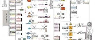
Priora controller connector: how to properly connect the alarm system
Installation of the security system is quite simple and the primary connection points for the Priora alarm system are located on the controller connectors. First of all, connection is made to X1: 12V power supply to the red wire (numbers 2,3), turn signals are connected to the blue and blue with a black stripe wire (pins 14 and 15).
This connection stage is responsible for the normal functioning of the turn signals during alarm installation. And in addition, they will guarantee the correct operation of this part of the car’s electronics.
Next, work is done with connector X2, to which the wires from the ignition and hood will be supplied and connected. To connect the ignition, you will need to connect the orange wire (numbered 9) to the connector. A white wire with a black stripe (pin 17) is connected from the hood. This work is carried out for the following cases:
1. Preventing an attacker from trying to open the hood.
2. Prevent attempts to damage or remove the battery.
3. Normalization of autorun operation.
4. Correct functioning of the protection system.
The next step will be for Priora to connect the connection points on the last X3 connector. The work is quite simple and consists of connecting the wires leading to the limit switches. For the front doors, you will need to connect the brown wire (pin 7) for the passenger door and the blue/black wire (pin 6) for the driver's door to the connector.
Next, connect the yellow wire with a red stripe (pin
from the trunk and a gray wire with a red stripe (pin 1) for the rear doors.
Repair of electric central locking
Central locking systems with solenoids are factory installed on domestic cars. Such systems begin to malfunction after a year or two, for example, the passenger door does not close from the central lock, or the central lock closes and opens immediately. The reason for this is the sensitivity of the system to humidity and temperature changes. The solenoids begin to “stick,” which subsequently leads to their complete failure. The way out of the situation is to disassemble each of them, clean and apply new lubricant. It is better to immediately replace the solenoids with drives with motors.
If the central locking does not close the rear doors, or other incomplete operation is noted, the reasons can be sought in the following:
- broken contact in the supply circuit;
- relay problems;
- poor contact on the motor/solenoid;
- wear of gears or other moving elements of the activator;
- burnt motor/coil winding.
In this case, it is optimal to start repairs by testing the power supply to the drive that does not operate. When you turn on the “close” mode on the remote control, power should flow to the first wire - this moment is recorded with a multimeter. When you try to open the central locking system, the voltage disappears on this wire and appears on another. If the test results are exactly like this, then the problem is in the drive itself, which is easier to replace with a new one, since not every malfunction can be eliminated, especially on your own.
If the problem is in the wiring, you will have to test the entire circuit up to the activator separately. The most common problem is a break in the wire running between the door and the body. Despite its placement in additional corrugated insulation, a break or break in this place is commonplace. Therefore, checking the wiring can be started from here, but if after restoring the wiring the power is not restored, the problem may lie in the relay or the wiring after it. Possible problems with central locking are described in the video:
Preparing for self-installation of central locking
The complexity of installation directly depends on the brand of car. But, in fact, cases when something needs to be filed and drilled out for a long time are rare. These mainly include long-lived cars, which are at least thirty years old. In most options, the car is already prepared for installation of the central locking system. All that remains is to put the kit in place. Well, the second side of the issue is the set itself. If you don’t want to dig around for a long time, buy universal locks. Installation is simple and you will find plenty of information on them.
What's in the basic kit?
We take the simplest universal kit. Control, in our case, will be carried out from a special key fob. Usually there are two. There is an option when the system will be activated by turning the key in the driver's door lock. You can also display a special button in the car interior. This additional option is very nice if you need to lock the doors while driving. It is not always convenient to use the control panel.
So, we purchase a universal lock kit, which in most cases includes:
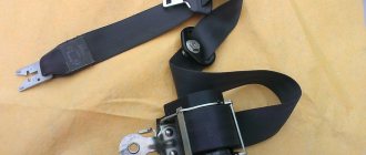
- Four motors. They will be attached to the door. One of them with four wires is on the driver's door;
- Control block. We will subsequently connect all the wires to it;
- A set of wires of the required length. If you feel that there are not enough of them, buy additional ones immediately;
- Key rings, strips, screws, etc.
central locking
Necessary tools for work
Now we are assembling a tool that will be useful to us in our work. If there are no holes for mounting motors in the doors, then prepare a drill with a drill bit. Also needed: screwdrivers, a screwdriver, a knife, corrugated tubes (wires are laid through them to avoid chafing and the influence of external factors on the wiring) and electrical tape. We will rewind all exposed sections of wires with tape in order to avoid their contact with metal parts of the body.
The last thing to do before proceeding with installation is to remove the trim and dust curtains from all doors. Determine the location where you will mount the mechanism so that it does not interfere with the operation of the window regulators. If necessary, you will have to make an additional bracket.
Installation of central locking
All necessary preparations have been made, and you can begin to work. We attach the motors to the doors, remembering that we place the motor with four wires on the driver's door. We also install the control unit there.
Connection diagram
After installation, we check the correct interaction with the lock rod, which is responsible for opening and closing the door, and the smooth operation of the lock itself.
Let's move on to the wires. We pull them from each motor to the control unit. Think in advance about how to pull the wire from the rear right door. You can use the space under the seats. We connect them according to the circuit and perform the test. To do this, return the battery to its previous state. If you find any faults, first check that the connections are correct. The plus and minus outputs may be confused. When checking, it is better to be inside the car or not to close the doors. Once you restore battery function, the locks should work automatically.
Installed and connected motor
If you still want to make a lock control button, prepare the missing parts in advance. Additional wire and button. It can be embedded into the dashboard. Buy any button, for example, for a window regulator.
Installation of the central locking control button
We look for the black, brown and white wires under the side panel and connect to them. Alternatively, you can stretch the wires and connect to the electrical bundle from the central locking of the driver's door. And we carry out the rest of the connection according to the diagram.
Connection diagram for the central locking control button
Connection diagram for the central locking control button
It is absolutely not necessary to make this button on the panel. Again, it all depends on convenience. You can place it in the space between the front seats if the necessary electrics are there. Alternatively, the button can be embedded in the armrests on the doors.
The trunk can also be connected to the central locking. Which, by the way, will also significantly save your time and nerves. If you have a wiper on the rear window, then the necessary electrical wiring is already installed, and connecting will not be difficult. The main thing is not to forget that central locking still cannot secure your car one hundred percent. Such options must be used comprehensively and, of course, an alarm system must be installed.
Lock repair
We figured out why the central locking does not close the door. Statistics show that half of the problems are related to wiring and electronics, and the second are related to mechanics.
As for repairs, domestic locks are very afraid of temperature changes and high humidity. The activators first jam, and then completely refuse to open/close the locks. Typically, such drives can be found on domestic cars. It is better to replace such activators with separate drives. But you can also disassemble, thoroughly clean and lubricate.
Features of connecting the alarm to the lock on the driver's door
Installing a central lock on the driver's door allows the owner to avoid the main reason for car theft: opening one of the passenger doors. That is why you should carefully study the car alarm connection points on the Priora in order to ensure maximum protection and ease of use of the vehicle.
For the central locking to function, you will need to connect two wires to the driver's door. They should be triggered by a break in the brown wire when the lock is closed and, accordingly, the locking buttons are activated.
For the modern Lada Priora, the alarm connection points responsible for the normal operation of the autostart are also very important. You will need to connect a brown wire with a red streak to the dashboard connector. And the brown/white wire is connected to the generator. All this allows you to control the autostart procedure. The last connection point will be the brown/blue wire from the handbrake.
Upon completion of the full procedure for searching for points and connecting the corresponding wires to them, you need to visually evaluate the connections and check the operation of the alarm in action. Until the moment of complete reliability in the correct functioning, the Lada Priora alarm connection points must remain open.
This will allow you to immediately begin correcting them if any problems are detected. Once the goal is achieved, the plastic of the front panel and tunnels can be replaced.
Repair of electric central locking
Electric central locks on cars are sensitive to temperature changes and high air humidity. At first they start to freeze and after a short time they refuse to work.
Causes of malfunction of the electrical central locking system:
1.Breakage of electrical circuit wires.
Careless actions when dismantling doors or repairing them lead to a break in the electrical wire in the corrugations. It is necessary to “ring” the electrical circuit to find damage.
2. Relay failure.
The damaged relay is replaced and the system operates as before.
3. Malfunctions of the control board.
It is being repaired or replaced.
4. Wear of motor gears.
Active use of the central locking system leads to wear and tear on the working elements of the motor. Plastic gears suffer. They wear out as a result of work. They are being replaced.
The central locking system in a car is a useful and convenient feature for the driver. To repair it, you need to understand the structure and principle of operation. Thank you for your attention, good luck on your journey. Read, comment and ask questions. Subscribe to fresh and interesting articles on the site.
Why is everything so difficult?
It would seem that we only need to manage the locks. Why then connect to the window lift motors?
All relays operate simultaneously
The opening of the passenger doors is carried out by the second impulse (relay K1 is activated). And elements K2 and K3 at this moment block the power windows. If they are not blocked, the windows in the doors will lower during the entire control pulse. And even in 0.8 seconds they will open noticeably.
Of course, connecting the signaling system in a Priora is more difficult than in many domestic cars. At the same time, the “Grant” in the “Norma” configuration uses a similar scheme. Be that as it may, the Lada Priora is the flagship of VAZ. And probably, difficulties with the electrical part should not confuse a competent car owner. It is also known that the standard control unit can be reprogrammed, and then unlocking occurs in one step. In this case, the connection is made according to “Scheme 1”.
If the central locking system does not work
When the central locking opens but does not close the doors, or there are other problems, and the car is equipped with an alarm, the check begins with testing it. If the central locking does not work from its remote control, but works fine from its own or from a button, the reason is the alarm. If this is not the reason, you will have to tinker. A complete failure of the central locking system is characterized by barely audible clicks from the drives; the buttons for manually opening the doors will remain motionless.
In this case, the first thing you need to do is check the fuse leading to the central locking. You should first clarify the central locking circuit, since there may be several fuses. Very often it is at this stage that the repair ends. If one of them fails, you should know that this indicates a short circuit in its circuit, and the check must be carried out taking this into account.